System and Method for Regeneration of a Fluid

a fluid regeneration and fluid technology, applied in the field of fluid regeneration systems and methods, can solve the problems of patient weight variation, waste products accumulate between treatments, and the body is exposed to highly varying concentrations,

Inactive Publication Date: 2009-05-07
TRIOMED AB
View PDF5 Cites 46 Cited by
  • Summary
  • Abstract
  • Description
  • Claims
  • Application Information

AI Technical Summary

Benefits of technology

[0014]In a still further embodiment, the system may comprise an ultrafiltration filter connected to a retentate outlet of said filtering device, the permeate of said ultrafiltration filter being returned to said compartment and the retentate of said ultrafiltration filter being passed to said filtering device for concentration. Each pump arranged immediately before the inlet of said filtering device may be a powerful pump arranged for providing a pressure sufficient for passing substantially only water through the membrane of the filtering device. A valve may be connected to the retentate outlet of said separation filter for directing the outlet fluid to said ultrafiltration filter and / or to said compartment. A circulation pump may be arranged between the inlet and the retentate outlet of any one of said separation filter, said ultrafiltration filter and said filtering device, for increasing the tangential flow of fluid over said membrane of each filter.

Problems solved by technology

The drawback with conventional hemodialysis, as described above, is that the waste products accumulate between the treatments and the body is exposed to highly varying concentrations of e.g. urea and creatinine in the body fluids.
Moreover, the patient cannot get rid of excess fluid between the treatments, which results in that the weight of the patient varies e.g. 4 kg between the treatments.
The apparatus according to U.S. Pat. No. 4,269,708 is, however, too heavy to be convenient to carry all the time.

Method used


Image

  • System and Method for Regeneration of a Fluid
  • System and Method for Regeneration of a Fluid
  • System and Method for Regeneration of a Fluid

Examples


Embodiment Construction

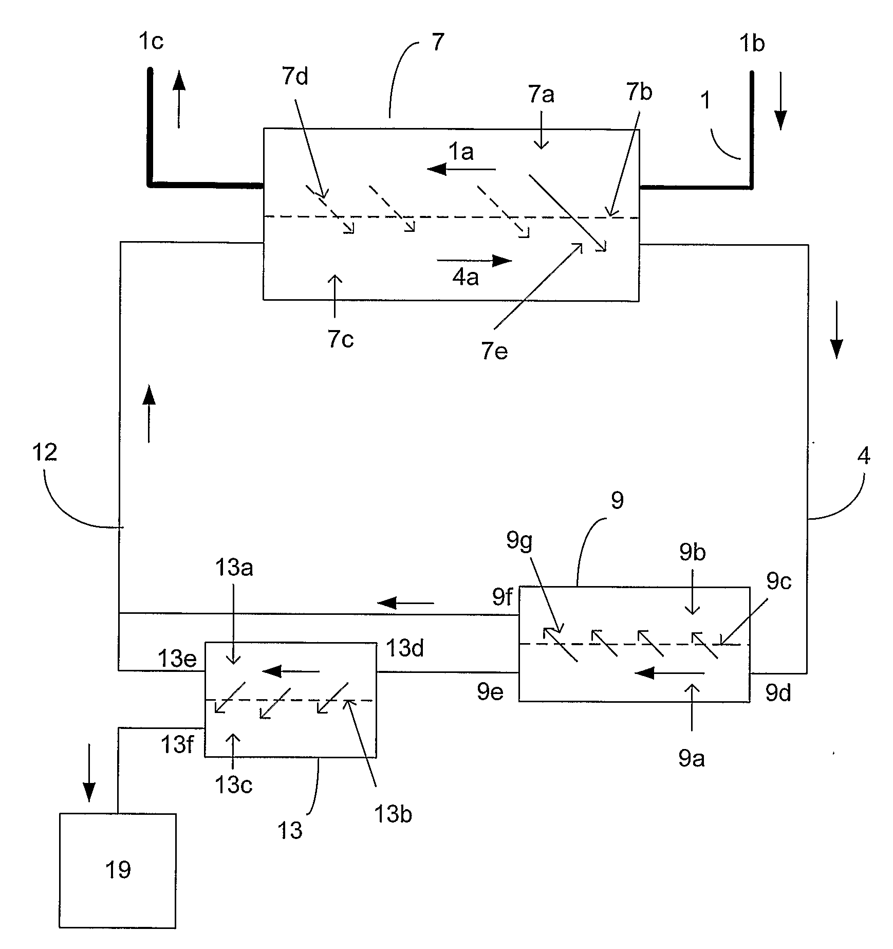
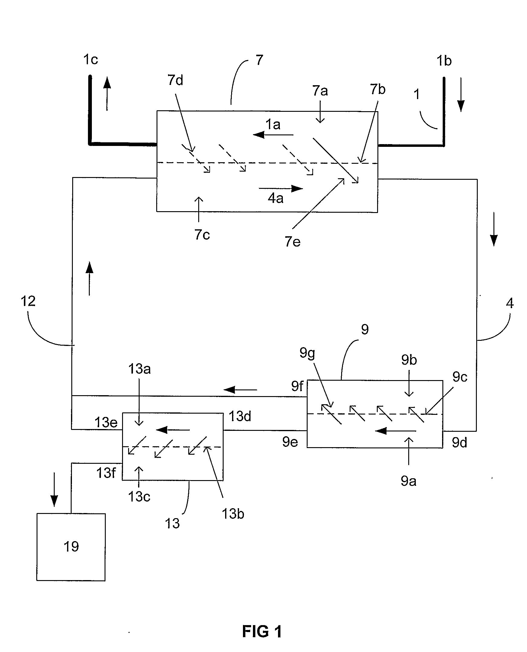
[0041]An embodiment of a fluid regeneration system for blood purification is shown in FIG. 1. The system comprises a blood filter 7, which is an ultrafilter or dialysator, comprising a blood compartment 7a and a dialysate compartment 7c separated by a semipermeable membrane 7b. In the blood compartment 7a, blood is circulated through a blood circuit 1 as shown by arrow Ia. Dialysate or dialysis fluid is circulated in the dialyser compartment 7c as shown by arrow 4a, normally in a counterflow.

[0042]Blood circuit 1 may comprise a first needle or catheter connected to inlet line Ib and a second needle or catheter connected to outlet line Ic. The needles or catheters may be inserted in blood vessels or a single blood vessel of the mammal being treated by the system. The needles may be inserted in a fistula arranged in the arm of a patient. Alternatively, catheters may be inserted in suitable arteries and / or veins of the patient. In the case a first catheter is inserted in the artery and...


PUM

PropertyMeasurementUnit
weightaaaaaaaaaa
flow rateaaaaaaaaaa
pressureaaaaaaaaaa

Abstract

A system comprising a blood circuit including a membrane arranged in a blood filter (7) in which blood is in contact with a first side of said membrane; and a dialysis circuit in which a dialysis fluid is in contact with the other side of the membrane for exchange of substances and ions through the membrane as well as water. The dialysis fluid is circulated from a dialysis compartment and through a RO filter (9). The permeate fluid, i.e. water is returned to the dialysis compartment. The retentate fluid from the RO filter (9) passes through a separation filter (13). The retentate fluid is returned to the dialysis compartment and the permeate fluid is removed from the dialysis circuit as a waste fluid to a receptacle (19). The retentate fluid is concentrated in the RO filter in a ration of at least 3:1.

Description

[0001]The present invention relates to a method and system for regeneration of a fluid for a blood purification system for removal of soluble products from a body fluid, which is arranged to be permanently connected to a patient and being portable so that the patient can bring the system with himself. The system is particularly intended for removal of waste products from the blood of a patient having impaired or no kidn.ey function.BACKGROUND OF INVENTION[0002]Patients having impaired or no kidney function are normally treated by dialysis. Hemodialysis may take place e.g. during four hours each second day. During hemodialysis, the blood of the patient is circulated in an extra-corporeal circuit and passed through a dialysator having a semipermeable membrane, one side of which being in contact with the blood. The other side of the semipermeable membrane is in contact with a dialysis fluid having a certain composition. Waste products such as urea and creatinine may pass from the blood...

Claims


Application Information

Patent Timeline
Patent Type & Authority Applications(United States)
IPC IPC(8): A61M1/16B01D61/24
CPCA61M1/1696A61M1/287A61M1/3472B01D61/145B01D63/16A61M1/3482B01D2313/24B01D2313/243B01D2315/02A61M1/3465A61M1/3468B01D2313/08
Inventor WALLENAS, ANDERSWRAMNER, LARS
Owner TRIOMED AB
Why Eureka
Try Eureka