Liquid-gap electrostatic hydraulic micro actuators

a micro actuator and electrostatic technology, applied in the direction of generator/motor, valve operating means/releasing devices, mechanical equipment, etc., can solve the problems of inability to be used in a wide range of flow conditions, no micro devices that utilize non-conducting liquid for electrostatic actuation and hydraulic force transfer, and limited force and deflection of typical air-gap electrostatic actuators. to achieve the effect of reducing the required voltag

Inactive Publication Date: 2009-05-07
RGT UNIV OF MICHIGAN
View PDF6 Cites 44 Cited by
  • Summary
  • Abstract
  • Description
  • Claims
  • Application Information

AI Technical Summary

Benefits of technology

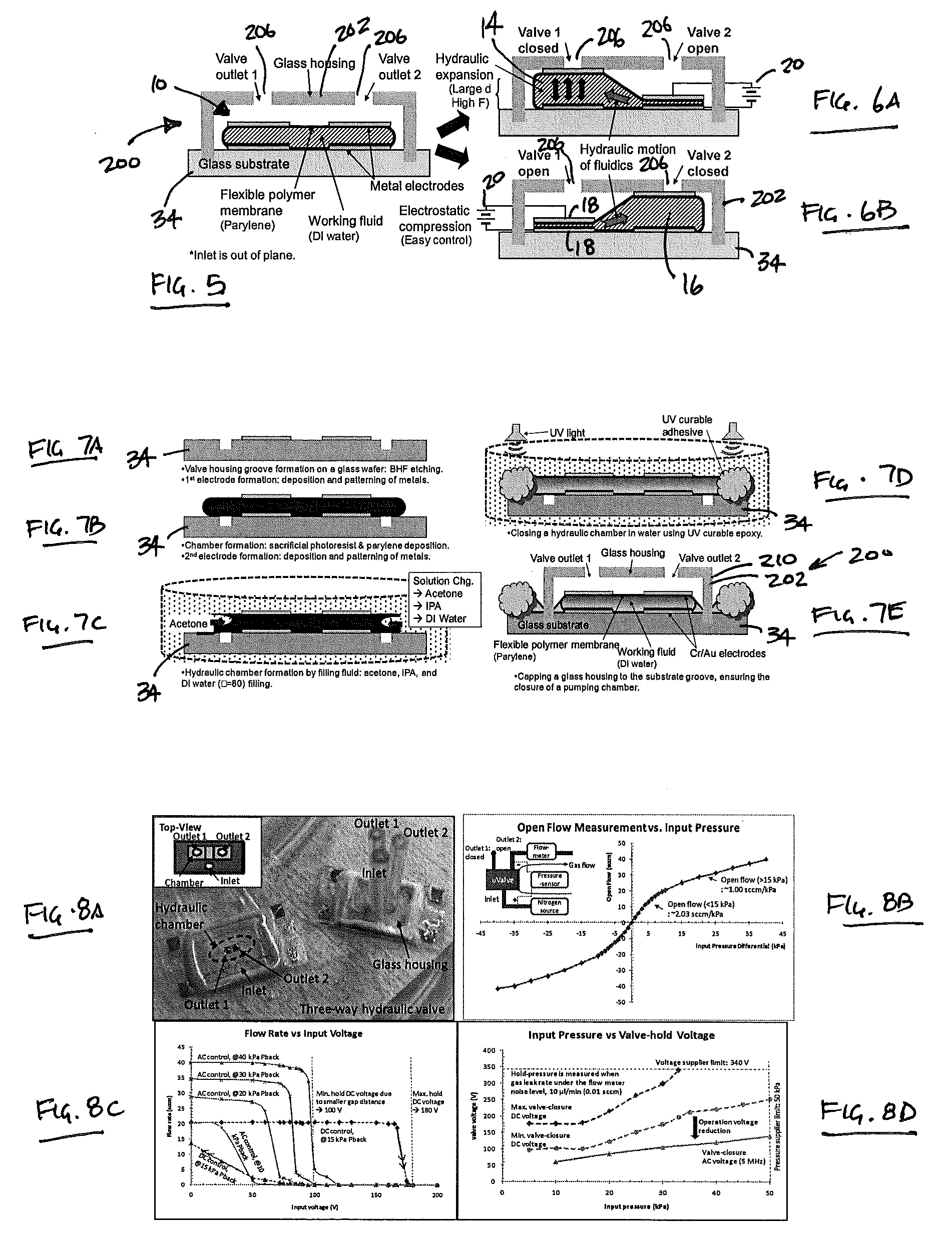
[0063]In some embodiments, as illustrated in FIG. 8A, the micro valve 200 was operated under different voltages and input gas pressures. First, each chamber 14, 16 was actuated using both DC and AC (5 MHz) signals and gas flow was monitored through output ports 206. Then, the chambers 14, 16 were operated under different voltages and variable loads between 10 kPa and 50 kPa. The micro valve 200 allowed symmetric high open-flow-capacity of 20.3 sccm at 10 kPa through both outlets (see FIG. 8B). Micro valve 200 could actuate against a maximum pressure of 50 kPa (the pressure source limit) using an AC voltage of 120V, while a much higher DC voltage (>340V) was required...

Problems solved by technology

However, typical air-gap electrostatic actuators produce limited force and deflection in the micro domain because the air gap distance, which determines the maximum deflection, cannot be large enough to obtain sufficient mechanical force.
Although electrostatic actuation in aqueous environments has been investigated, no micro devices that utilize non-conducting liquid for electrostatic actuation and hydraulic force transfer have been reported.
However, these attempts suffered from a number of disadvantages, such as their inability to be used in wide range ...

Method used


Image

  • Liquid-gap electrostatic hydraulic micro actuators
  • Liquid-gap electrostatic hydraulic micro actuators
  • Liquid-gap electrostatic hydraulic micro actuators

Examples


Embodiment Construction

[0033]Example embodiments will now be described more fully with reference to the accompanying drawings. Numerous specific details are set forth such as examples of specific components, devices, and methods, to provide a thorough understanding of embodiments of the present disclosure. It will be apparent to those skilled in the art that specific details need not be employed, that example embodiments may be embodied in many different forms and that neither should be construed to limit the scope of the disclosure.

[0034]The terminology used herein is for the purpose of describing particular example embodiments only and is not intended to be limiting. As used herein, the singular forms “a”, “an” and “the” may be intended to include the plural forms as well, unless the context clearly indicates otherwise. The terms “comprises,”“comprising,”“including,” and “having,” are inclusive and therefore specify the presence of stated features, integers, steps, operations, elements, and / or component...


PUM

PropertyMeasurementUnit
Forceaaaaaaaaaa
Dielectric polarization enthalpyaaaaaaaaaa
Volumeaaaaaaaaaa

Abstract

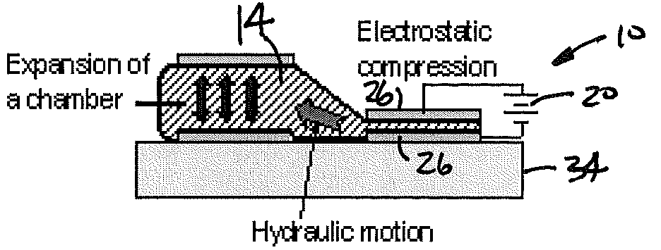
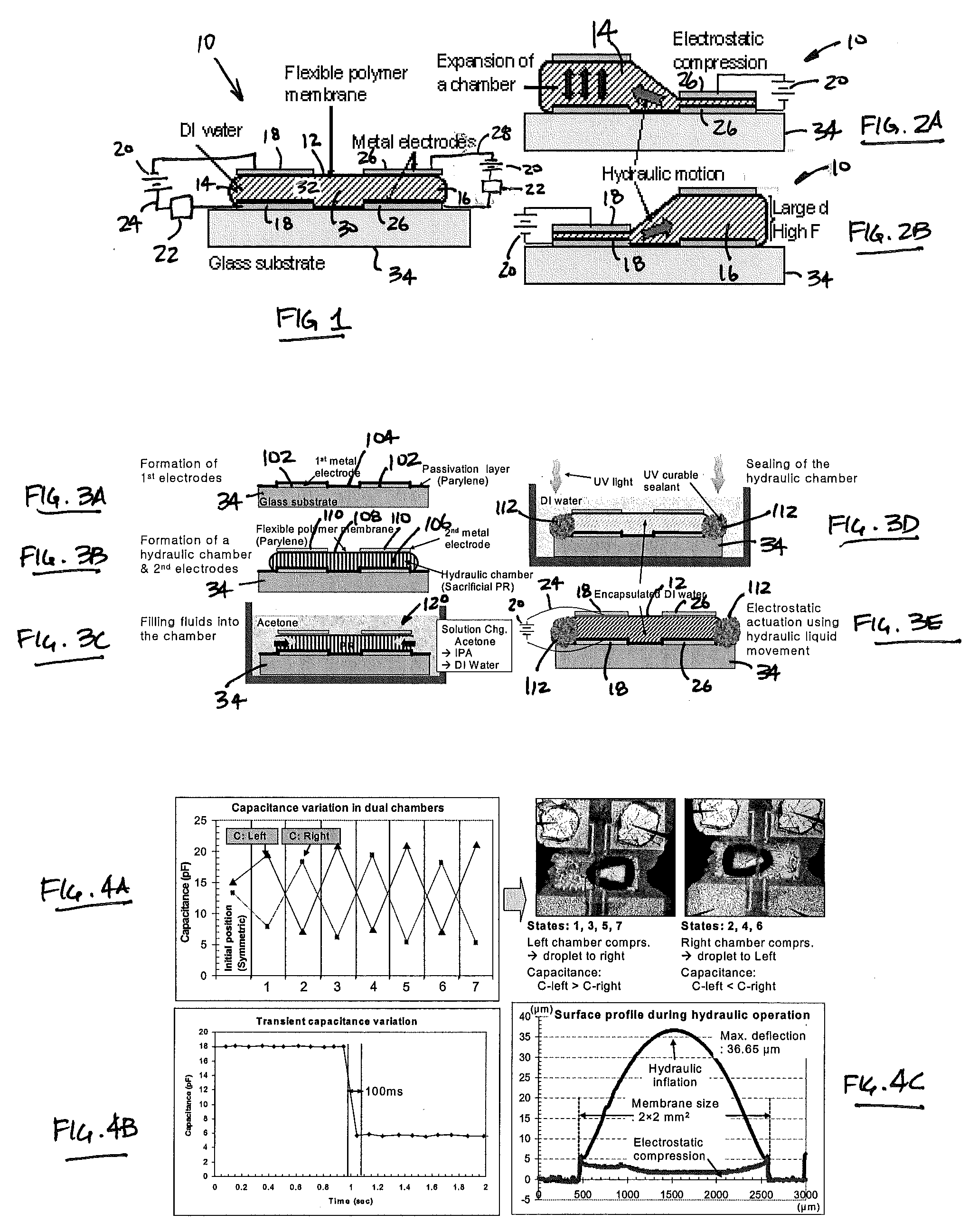
A liquid-gap electrostatic hydraulic micro actuator is provided that produces higher displacement (in and out of plane) and larger force than typical electrostatic actuators by utilizing a non-conducting liquid as its dielectric material. This new class of actuators utilizes the liquid dielectric for hydraulic amplification and force transfer. The liquid electrostatic actuator consists of two chambers each forming a parallel-plate capacitor, filled with a non-conducting incompressible liquid. One chamber is compressed by pulling down a flexible membrane using electrostatic actuation, thus forcing the liquid under it to transfer into the other chamber. Such movement causes the other chamber's membrane to expand out of plane.

Description

CROSS-REFERENCE TO RELATED APPLICATIONS[0001]This application claims the benefit of U.S. Provisional Application No. 60 / 997,768, filed on Oct. 8, 2007. The entire disclosure of the above application is incorporated herein by reference.GOVERNMENT RIGHTS[0002]This invention was made with government support under EEC-9986866 awarded by the National Science Foundation. The government has certain rights in the invention.FIELD[0003]The present disclosure relates to electrostatic micro actuators and, more particularly, to liquid-gap electrostatic hydraulic micro actuators.BACKGROUND AND SUMMARY[0004]This section provides background information related to the present disclosure which is not necessarily prior art. Additionally, this section provides a general summary of the disclosure, and is not a comprehensive disclosure of its full scope or all of its features.[0005]Electrostatic micro actuators have been widely used for numerous applications, such as gas micropumps, micro valves, and opt...

Claims


Application Information

Patent Timeline
IPC IPC(8): H02N11/00F16K31/02H04R17/00
CPCF15B7/00Y10T29/42F15B15/10
Inventor NAJAFI, KHALILKIM, HANSEUP
Owner RGT UNIV OF MICHIGAN
Why Eureka
Try Eureka