Discharge control system

a technology of discharge control and control system, which is applied in the direction of battery/fuel cell control arrangement, transportation and packaging, and arrangement of several simultaneous batteries, etc., can solve the problem of long time spent on uniform cell voltages of cells, and achieve good efficiency and consumption of energy

Inactive Publication Date: 2009-05-07
HONDA MOTOR CO LTD
View PDF7 Cites 38 Cited by
  • Summary
  • Abstract
  • Description
  • Claims
  • Application Information

AI Technical Summary

Benefits of technology

[0012]The invention provides a discharge control system which can consume energy stored in a electric storage pack with good efficiency.

Problems solved by technology

However, with a small discharge current, a longer time has to be spent in making uniform the cell voltages of the cells.

Method used


Image

  • Discharge control system
  • Discharge control system
  • Discharge control system

Examples


first embodiment

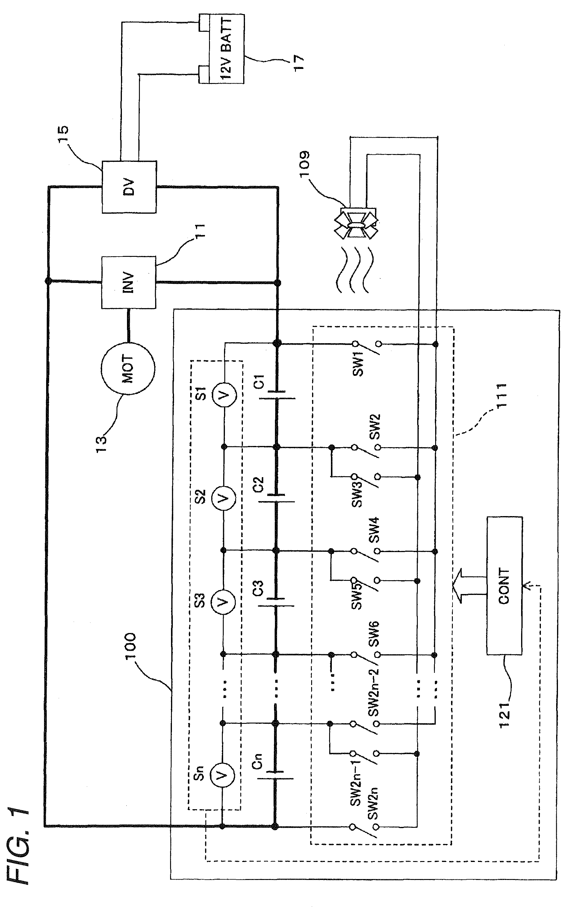
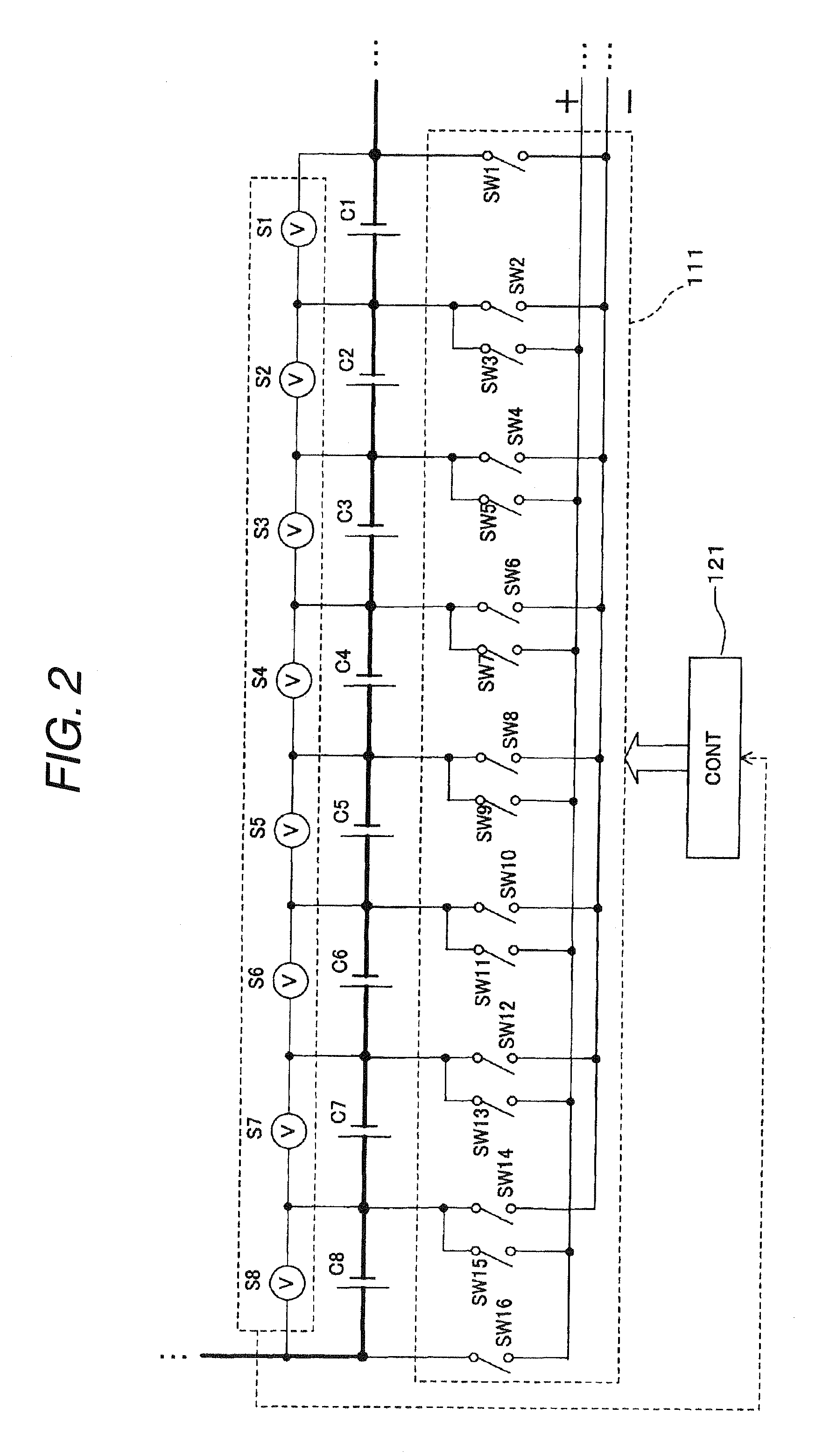
[0050]FIG. 1 is a block diagram showing a relationship between a electric storage pack according to a first embodiment, part of an electric drive system and auxiliaries which are equipped on a vehicle. The vehicle described in FIG. 1 includes a electric storage pack 100 of the first embodiment, an inverter 11, a motor 13, a DC-DC converter 15, a battery 17, and a cooling fan electric motor (hereinafter, referred to as an “electric motor”) 109 which is a rotary induction load. The inverter 11, the motor 13, the DC-DC converter 15 and the battery 17 are the same as those constituent elements shown in FIG. 23.

[0051]An output voltage of the electric storage pack 100 of this embodiment is a high output voltage (for example, 100 to 200V), and an output voltage of the battery 17 is an output voltage for auxiliaries (for example, a low voltage of 12V). The output voltage of the electric storage pack 100 is transformed from direct current to alternating current by the inverter 11 for supply ...

second embodiment

[0090]While in the first embodiment, the continuous discharge line is formed from at least one cell to the cooling fan electric motor 109 which is the rotary induction load by the on / off control of the switches SW1 to SW2n by the control unit 121, in a second embodiment, a discharge line is formed from a cell of cells installed in a electric storage pack 100 which has a highest cell voltage to an electric motor 109. Although a relationship between the electric storage pack, part of an electric drive system and auxiliaries is substantially the same as that of the first embodiment shown in FIG. 1, a control unit possessed by the electric storage pack performs a different on / off control of switches SW1 to SW2n from the on / off control performed by the control unit 121 of the first embodiment.

[0091]Hereinafter, a discharge control by a control unit of the second embodiment will be described by reference to FIGS. 15 and 16. FIG. 15 is a flowchart illustrating the discharge control by the ...

third embodiment

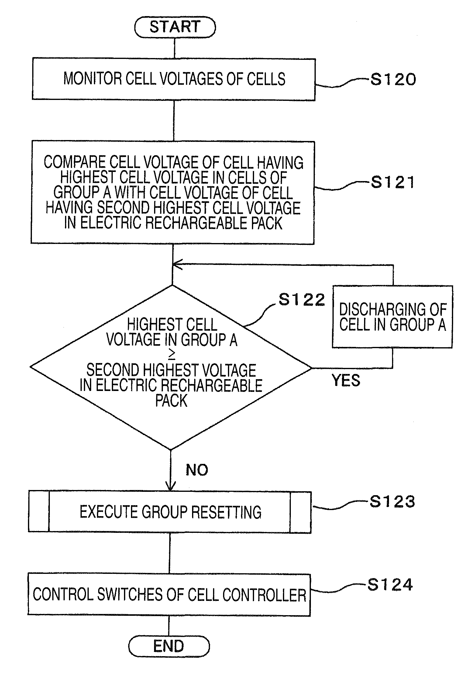
[0097]A third embodiment is identical to the second embodiment in that a discharge line is formed from a cell having a highest cell voltage in cells installed in a electric storage pack 100 to an electric motor 109 but is different therefrom in timing at which discharge lines are switched. Namely, while in the second embodiment, discharge continues until the cell voltage of the discharging cell drops to the cell voltage of the cell having the lowest cell voltage in the cells installed in the electric storage pack, in the third embodiment, discharge continues until the cell voltage of a discharging cell drops to be a voltage resulting from subtraction of a predetermined voltage from the cell voltage of a cell having a second highest cell voltage in the cells in the electric storage pack.

[0098]Although a relationship between the electric storage pack of the third embodiment, part of an electric drive system and auxiliaries is substantially the same as that of the first embodiment show...


PUM


Abstract

A discharge control system of a electric storage pack has a plurality of electric rechargeable cells connected in series and a discharge line is connected from a electric rechargeable cell to a load driving feeding circuit. The discharge control system includes cell voltage detection units for detecting respective cell voltages of the plurality of cells, a switch group made up of a plurality of switches connected between the plurality of cells, and a control unit which designates a cell having a highest cell voltage in the plurality of electric rechargeable cells possessed by the electric storage pack in accordance with detection results by the cell voltage detection units and on/off controls the switches of the switch group individually so as to form a discharge line from a electric rechargeable cell of the group to the load driving feeding circuit.

Description

FIELD OF THE INVENTION[0001]The present invention relates to a discharge control system for controlling discharge from a plurality of electric rechargeable cells included in a electric storage pack so as to make uniform residual capacities or states of charge of the respective electric rechargeable cells.DESCRIPTION OF RELATED ART[0002]A electric storage pack for supplying electric power to a motor or the like is equipped on a vehicle such as EV (Electric Vehicle) or HEV (Hybrid Electrical Vehicle). The electric storage pack includes a plurality of electric rechargeable cells which are connected in series.[0003]FIG. 23 is a block diagram showing a relationship between a electric storage pack, part of an electric drive system and auxiliaries which are equipped on a vehicle. The vehicle described in FIG. 23 includes a electric storage pack 10, an inverter 11, a motor 13, a DC-DC converter 15, a battery 17 and a cooling fan electric motor (hereinafter, referred to as an “electric motor...

Claims


Application Information

Patent Timeline
Patent Type & Authority Applications(United States)
IPC IPC(8): H02J7/00H02J7/02
CPCB60L11/1861B60L11/1864H02J7/0016Y02T10/7061Y02T10/7044Y02T10/7055Y02T10/7005B60L58/21B60L58/15Y02T10/70
Inventor NAGANUMA, ATSUHIROUCHIDA, SHINTARO
Owner HONDA MOTOR CO LTD
Why Eureka
Try Eureka