
Organic light emitting diode display and method for manufacturing the same

Active Publication Date: 2009-05-07
SAMSUNG DISPLAY CO LTD
View PDF4 Cites 75 Cited by
  • Summary
  • Abstract
  • Description
  • Claims
  • Application Information

AI Technical Summary

Benefits of technology

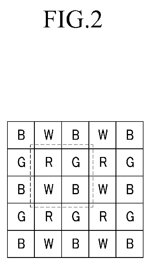
[0042]In an exemplary embodiment of the present invention, the color reproducibility and luminance may be improved by using the micro-cavity. Further, at least two pixels among the plurality of pixels displaying the different colors from each other have the same optical path lengths such that the number of processes for forming the different optical path lengths for each pixel may be reduced.

Problems solved by technology

In addition, the LCD has additional drawbacks such as a slow response time and a narrow viewing angle.
That is, a material having low light emitting efficiency among red, green and blue cannot represent the colors of a desired color coordinate, and it is also difficult to display a desired white color due to the material having the low light emitting efficiency in the case of emitting white color by combining red, green and blue.
Accordingly, light of a specific wavelength is constructive, and light of remaining wavelengths is destructive.

Method used


Image

  • Organic light emitting diode display and method for manufacturing the same
  • Organic light emitting diode display and method for manufacturing the same
  • Organic light emitting diode display and method for manufacturing the same

Examples


Embodiment Construction

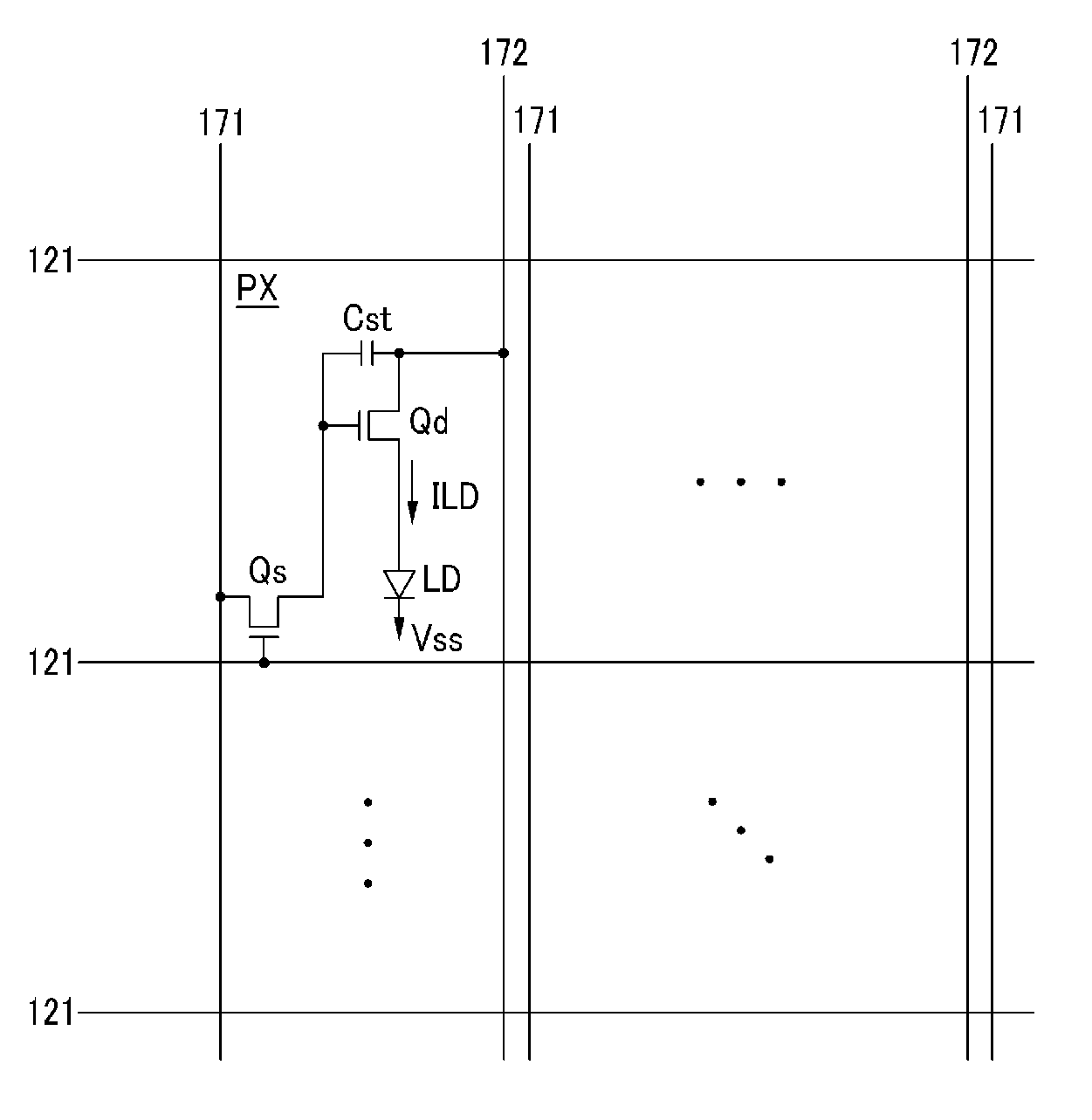
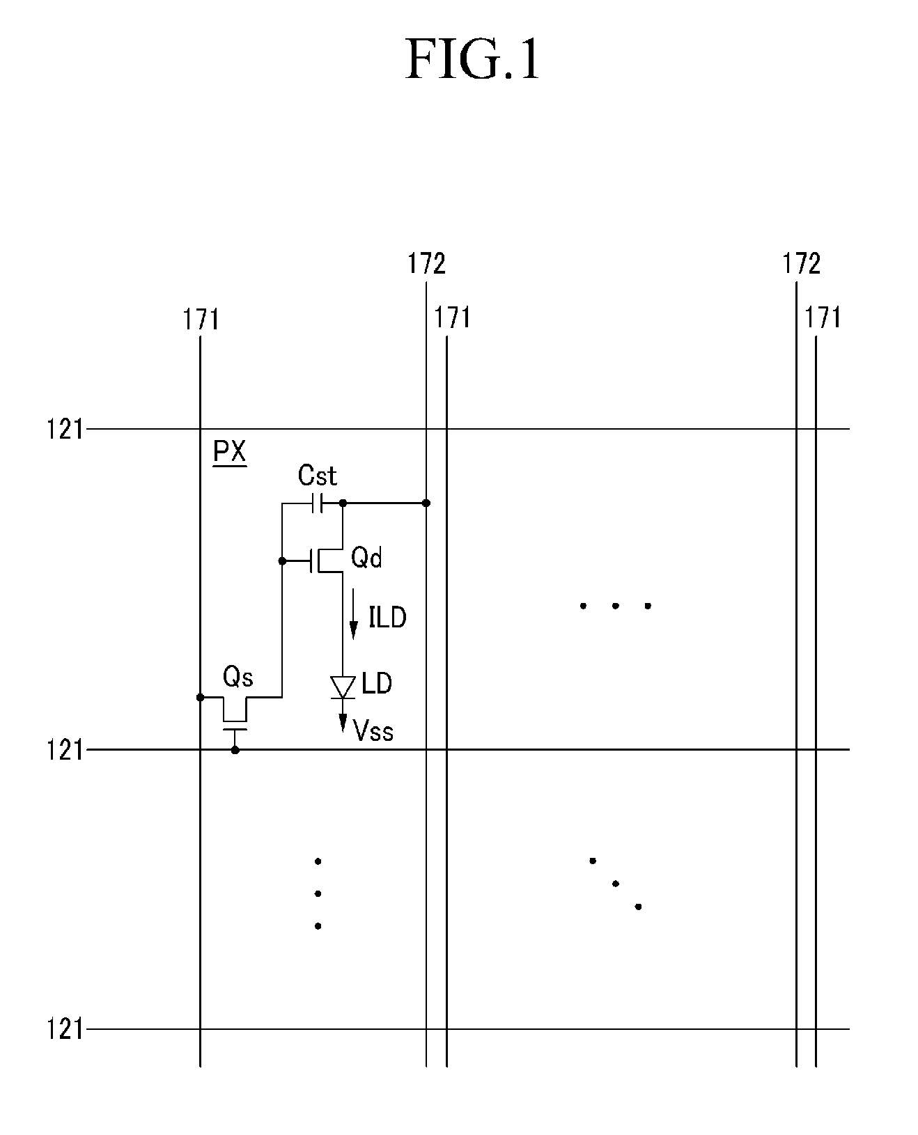
[0051]The invention is described more fully hereinafter with reference to the accompanying drawings, in which exemplary embodiments of the invention are shown. The present invention may, however, be embodied in many different forms and should not be construed as being limited to the embodiments set forth herein. Rather, these embodiments are provided so that this disclosure will be thorough and complete, and will fully convey the scope of the invention to those skilled in the art. Like reference numerals refer to like elements throughout.

[0052]It will be understood that when an element or layer is referred to as being “on”, “connected to” or “coupled to” another element or layer, it can be directly on, connected or coupled to the other element or layer or intervening elements or layers may be present. In contrast, when an element is referred to as being “directly on,”“directly connected to” or “directly coupled to” another element or layer, there are no intervening elements or layer...


PUM


Abstract

An organic light emitting device including a first pixel, a second pixel and a third pixel displaying different colors from each other according to the present invention, the organic light emitting device includes a reflecting electrode and a translucent member forming a micro-cavity along with the reflecting electrode, wherein a optical path length is an interval between the reflecting electrode and the translucent member, and wherein the light path lengths of at least two pixels among the first pixel, the second pixel and the third pixel are the same.

Description

[0001]This application claims priority to Korean Patent Application No. 10-2007-0112255, filed on Nov. 5, 2008, and all the benefits accruing therefrom under 35 U.S.C. § 119, the contents of which in its entirety are herein incorporated by reference.BACKGROUND OF THE INVENTION[0002](a) Field of the Invention[0003]The present invention relates to an organic light emitting diode display and a manufacturing method thereof.[0004](b) Description of the Related Art[0005]Recent trends toward lightweight and thin personal computers and televisions sets have increased the desire for lightweight and thin display devices associated therewith. Flat panel displays, such as a liquid crystal display (“LCD”) satisfying such requirements, are being substituted for conventional cathode ray tubes (“CRTs”).[0006]However, because the LCD is a passive display device, an additional back-light as a light source is needed. In addition, the LCD has additional drawbacks such as a slow response time and a narr...

Claims


Application Information

Patent Timeline
IPC IPC(8): G09G3/30
CPCH01L27/3211H01L51/5265H01L27/3244H01L27/3213H10K59/351H10K59/12H10K59/876H05B33/28H05B33/22H10K50/852
Inventor HWANG, YOUNG-INLEE, BAEK-WOON
Owner SAMSUNG DISPLAY CO LTD
Learn More