Cooling auxiliary unit and cooling system

a technology of cooling auxiliary unit and cooling system, which is applied in ventilation systems, heating types, electrical apparatus casings/cabinets/drawers, etc., can solve the problems of difficulty in uniform cooling of electronic apparatus in the height direction, cooling air dropping in the vertical direction, and difficulty for maintenance personnel to enter between the electronic apparatus and the cooling auxiliary unit for maintenance, etc., to achieve the effect of reducing the effect of air curtain effect, increasing width and large air capacity

Inactive Publication Date: 2009-05-07
FUJITSU LTD
View PDF10 Cites 13 Cited by
  • Summary
  • Abstract
  • Description
  • Claims
  • Application Information

AI Technical Summary

Benefits of technology

[0008]A cooling auxiliary unit according to one aspect of the present invention used for an accommodation room configured to accommodate an electronic apparatus includes a duct member that stands up on an ventilation hole provided from the raised floor, and has an air passage connected to the ventilation hole, and an opening connected to the air passage, and a fan that moves air along the air passage. According to this cooling auxiliary unit, the fan moves air, e.g., ascends the cooling air and descends the warmed air. As a result, this configuration can ascend the cooling air to a high position of the electronic apparatus in ascending the cooling air, and prevent ascending of the warmed air and a stream of the warm air in descending the warm air.
[0009]The duct member may have a rectangular, circular, or polygonal section perpendicular to an upper vertical direction. The rectangular or polygonal shape is convenient when the electronic apparatus is arranged at least one of sides of the duct member. The circular shape is convenient when plural electronic apparatuses are arranged around the duct member. The cooling auxiliary unit may be arranged between a pair of electronic apparatuses, wherein where D is an interval between the pair of electronic apparatuses, the duct member may have a width Px in a direction parallel to the interval, which generally meets 3Px≦D≦10Px. When D is smaller than 3Px, it is difficult for a maintenance person to enter between the electronic apparatus and the cooling auxiliary unit for maintenances. When D is greater than 10Px, a distance between the electronic apparatus and the cooling auxiliary unit becomes too large, causing the cooling air to drop in the lower vertical direction. As a result, it becomes difficult to uniformly cool the electronic apparatus in the height direction, or to prevent a stream of the warmed air. The duct member may be made of resin. When the duct member is made of resin molding, the air passage and openings can be precisely and easily formed. The fan may be provided in the duct member. Thereby, a movement of the air in the air passage (ascending of the cooling air and descending of warmed air) can become efficiently.
[0010]The cooling auxiliary unit may further include a top plate that is fixed onto the duct member at a position higher than the electronic apparatus, and configured to shield the air passage. The top plate can prevent a stream of the warmed air for efficient cooling. A bottom surface of the top plate may be higher than the electronic apparatus in a vertical direction by 20 cm to 40 cm. When the distance is smaller than 20 cm, the top plate is too close to the electronic apparatus and is not preferable for some safety purposes. The distance greater than 40 cm lowers an air curtain effect due to the cooling air exhaled from the openings, and degrades a warmed air stream preventive effect.
[0011]A section of the duct member may have an increased width perpendicular to an upper vertical direction from a position at which the duct member is as high as the electronic apparatus to a position at which the top plate is fixed. This configuration increases an area of the openings, and thus the number of openings and the air capacity. A large air capacity can effectively prevent a stream of the warm air. The top plate may have a rectangular, circular, or polygonal section perpendicular to an upper vertical direction. The rectangular or polygonal shape is convenient when the electronic apparatus is arranged at least one of sides of the top plate. The circular shape is convenient when plural electronic apparatuses are arranged around the top plate.
[0014]The present invention can provide a cooling auxiliary system and a cooling system having high cooling efficiency.

Problems solved by technology

When D is smaller than 3Px, it is difficult for a maintenance person to enter between the electronic apparatus and the cooling auxiliary unit for maintenances.
When D is greater than 10Px, a distance between the electronic apparatus and the cooling auxiliary unit becomes too large, causing the cooling air to drop in the lower vertical direction.
As a result, it becomes difficult to uniformly cool the electronic apparatus in the height direction, or to prevent a stream of the warmed air.

Method used


Image

  • Cooling auxiliary unit and cooling system
  • Cooling auxiliary unit and cooling system
  • Cooling auxiliary unit and cooling system

Examples


Embodiment Construction

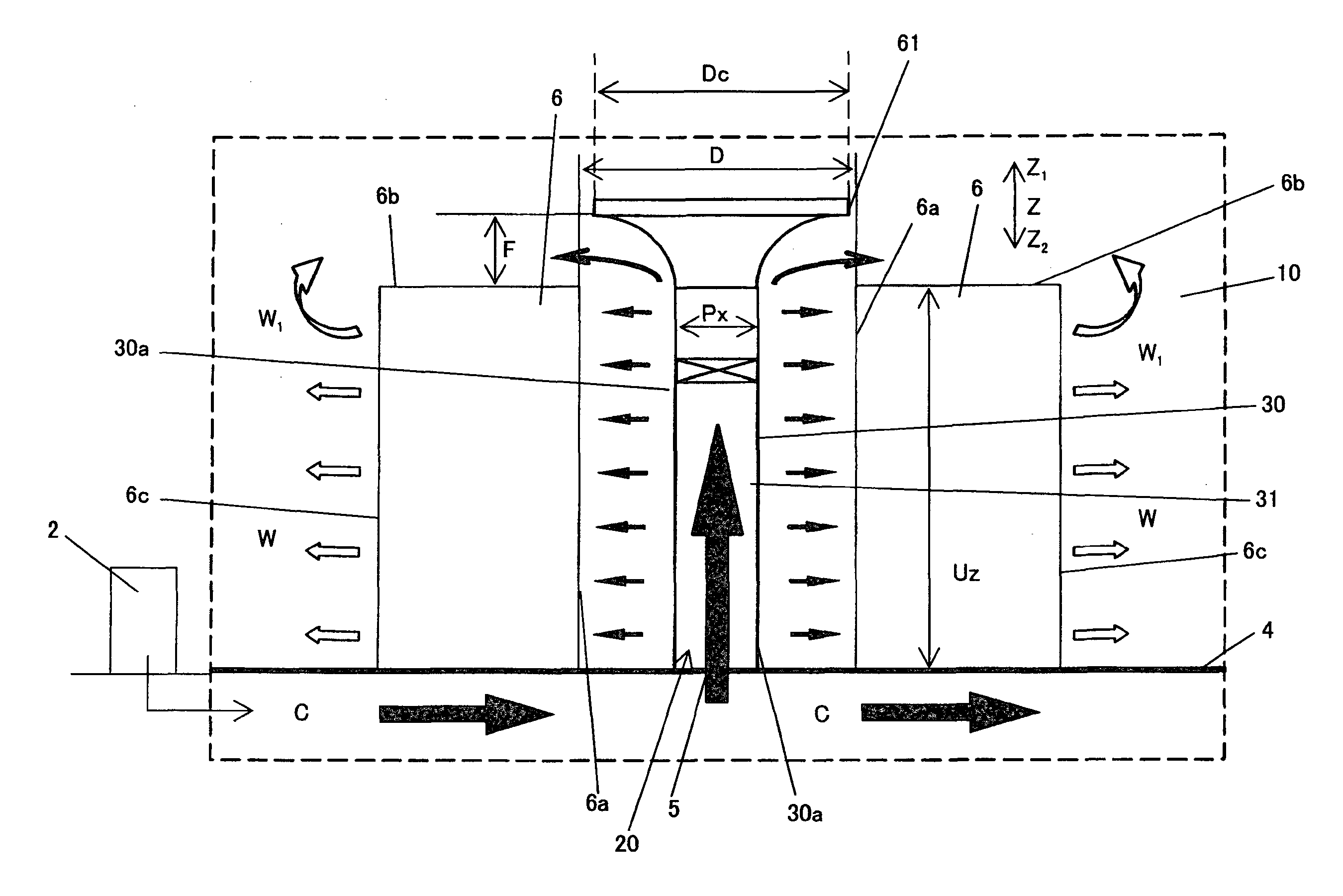
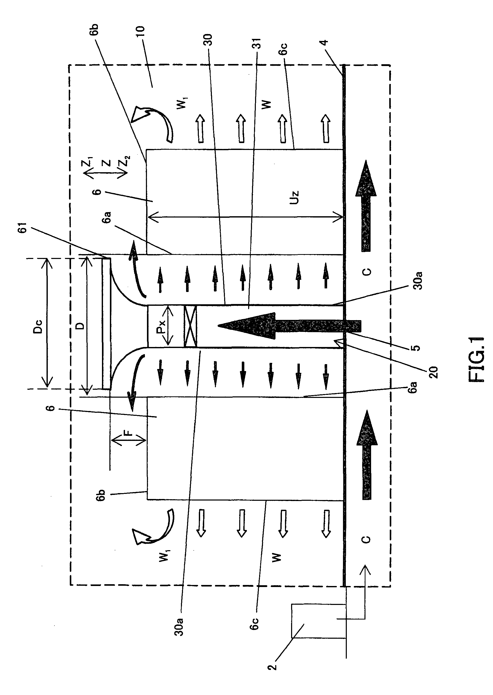
[0025]FIG. 1 is a schematic partially enlarged sectional view of an accommodation room 10. In FIG. 1, a vertical direction is a Z direction, and a horizontal direction is an X direction. An upper vertical direction is a Z1 direction, and a lower vertical direction is a Z2 direction. The accommodation room 10 is different from the accommodation room 1 shown in FIG. 8 in having plural cooling auxiliary units 20, and other than that, the accommodation room 10 has the same structure as the accommodation room 1. Thus, the accommodation room 10 is supplied with cooling air C from under the floor 4 via a ventilation hole 5 in the floor 4, and plural rack mount type servers 6 (electronic apparatuses) or servers (electronic apparatus) (not shown) installed in each rack mount type server 6. Therefore, those elements in FIG. 1, which are corresponding elements I FIG. 8, are designated by the same reference numerals, and a description thereof will be omitted.

[0026]The cooling auxiliary unit 20 ...


PUM


Abstract

A cooling auxiliary unit used for an accommodation room configured to accommodate an electronic apparatus includes a duct member that stands upon an ventilation hole provided on a raised floor, and has an air passage connected to the ventilation hole, and an opening connected to the air passage, and a fan that moves air along the air passage.

Description

BACKGROUND OF THE INVENTION[0001]1. Field of the Invention[0002]The present invention relates generally to a cooling auxiliary unit and a cooling system that utilizes it. The present invention is suitable for a computer accommodation room, or so-called data center, that houses plural servers, computers and electronic equipments, which will be referred to as an “accommodation room” hereinafter.[0003]2. Description of the Related Art[0004]As power dissipation increases along with the recently improving processing speed of a bulk computer, such as a server, the accommodation room has increasingly been required to have an efficient cooling capability. FIG. 8 is a schematic perspective view of a cooling system of a conventional accommodation room. Cooling air C supplied from under the floor 4 by an air conditioning machine 2 is introduced into an accommodation room 1 through a ventilation hole 5 of a floor 4. The floor 4 is raised having a space from a support member 3. Plural (four colu...

Claims


Application Information

Patent Timeline
Patent Type & Authority Applications(United States)
IPC IPC(8): H05K5/00
CPCH05K7/20745
Inventor JIE, WEITAKEMURA, KEIZOU
Owner FUJITSU LTD
Why Eureka
Try Eureka