Method for making airtight container

a container and airtight technology, applied in the manufacture of electrode systems, electric discharge tubes/lamps, semiconductor/solid-state device details, etc., can solve the problems of affecting the melting state of the joining member may not be sufficient, and it is difficult to keep the airtightness continuously over the entire joining portion, so as to improve the airtightness of the container and keep the melting state constan

Inactive Publication Date: 2009-05-14
CANON KK
View PDF27 Cites 21 Cited by
  • Summary
  • Abstract
  • Description
  • Claims
  • Application Information

AI Technical Summary

Benefits of technology

[0014]The present invention improves airtightness of a container by keeping constant the melting state of the joining member induced by laser.
[0016]According to the present invention, airtightness of an airtight container including two substrates and a frame member sandwiched between the substrates can be improved.

Problems solved by technology

In such a method for making an airtight container, the state of control of the laser beam that melts the joining member greatly affects the airtightness of the container.
However, the '599 document does not disclose what information regarding the reflected laser beam is used in controlling the laser power, thereby rendering the description ambiguous.
However, depending on the condition of the joining member, the joining member may not sufficiently melt even when the irradiation temperature is constant to achieve airtightness continuously over the entire joining portion.
For example, in the case where there is nonuniformity in thickness of an oxide film formed on the surface of the joining member, the oxide film may not dissipate even when the joining member is heated to its melting temperature, which renders it difficult to keep airtightness continuously over the entire joining portion.
However, this method is not a method that can continuously keep airtightness while monitoring the melting state of the laser-irradiated portion.
In all of the patent documents described above, it is difficult to continuously keep the substrates and the joining member closely adhered to each other, and airtightness has not always been achieved.
In joining a substrate to a frame member (or another substrate) by heat-melting the joining member through the substrate, these gaps obstruct heat transmission to the joining portion.
As a result, the melting state of the joining member becomes different from one position to another, and the joining member does not uniformly adhere to the substrate.

Method used


Image

  • Method for making airtight container
  • Method for making airtight container
  • Method for making airtight container

Examples


example 1

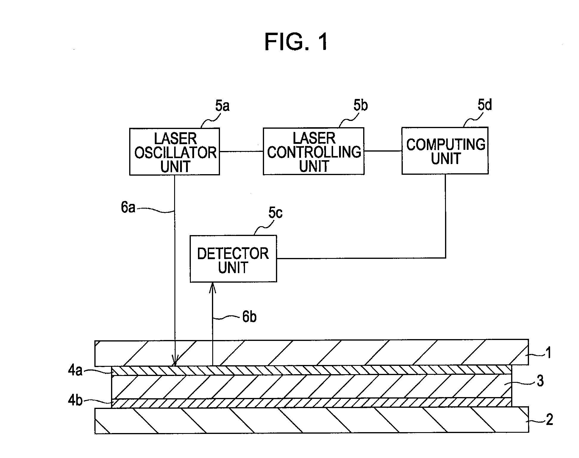
[0046]Example 1 of the present invention will now be described with reference to FIG. 1. Example 1 is related to a method in which a laser for melting the sealing member is also used for detecting the melting state of the sealing member. According to this example, only one laser oscillator unit is needed and thus the apparatus (mechanism) can be simplified.

[0047]In Example 1, glass substrates (PD200 produced by Asahi Glass Co., Ltd.) 300 mm×350 mm in size and 1.8 mm in thickness were used as the first substrate 1 and the second substrate 2. A frame having a rectangular shape in plan 280 mm×330 mm in size and 1.8 mm in thickness prepared from a glass substrate was used as the supporting frame 3.

[0048]First, the supporting frame 3 with the sealing member 4b applied thereon was disposed on the second substrate 2 and baked in an atmospheric furnace to join the second substrate 2 to the supporting frame 3 with the sealing member 4b. In this example, frit glass LS-7305 (produced by Nippon...

example 2

[0057]FIG. 4 shows the structure of an apparatus for implementing a method according to Example 2 of the present invention. The same structural units as those of the apparatus of Example 1 are represented by the same reference numerals.

[0058]In Example 1 described above, changes in reflectance were detected by using the reflection 6b of the laser beam 6a for melting the sealing member 4a. In contrast, in Example 2, a light source unit 41 for oscillating a laser beam 42a, which was a reference beam for detecting changes in reflectance, was provided separately from the laser oscillator unit 5a. In other words, a plurality of laser oscillator units were used so that a laser beam for melting the joining member is different from a laser beam for detecting the melting state.

[0059]In particular, the laser beam 42a (second laser beam) emitted from the light source unit 41 irradiated the portion of the sealing member 4a melted by the laser beam 6a (first laser beam). As a result, a reflectio...

example 3

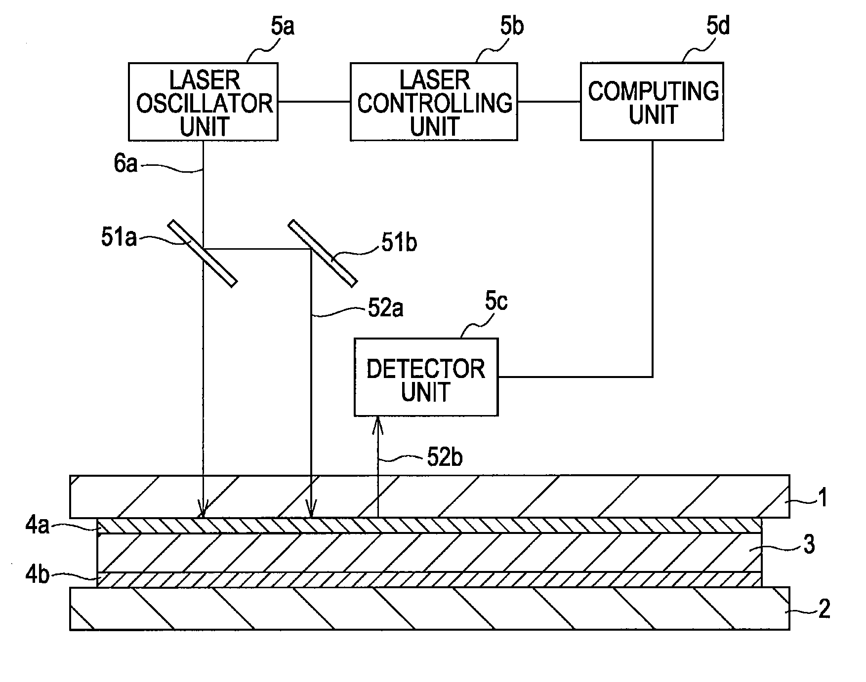
[0064]FIG. 5 shows the structure of an apparatus for implementing a method according to Example 3 of the present invention. The same structural units as those of the apparatus of Example 1 are represented by the same reference numerals.

[0065]In Example 1 described above, changes in reflectance were detected by using the reflection 6b of the laser beam 6a for melting the sealing member 4a. In contrast, in Example 3, a reference beam 52a for detecting changes in reflectance was formed by splitting the laser beam 6a with a partial reflector mirror 51a. In other words, a laser beam oscillated from the laser oscillator unit 5a was split into a laser beam for melting the joining member and a laser beam for detecting the melting state with a splitting mechanism. According to this structure, the power of the laser beam suitable for melting the joining member and the power of the laser beam (light source) suitable for measuring the reflectance can be selected. Moreover, since only one laser ...


PUM

PropertyMeasurementUnit
sizeaaaaaaaaaa
sizeaaaaaaaaaa
sizeaaaaaaaaaa

Abstract

A laser beam emitted from a laser oscillator unit passes through a first substrate and irradiates a sealing member. The sealing member irradiated with the laser beam is heated in accordance with the absorptance and thus softens and melts. The laser beam is reflected by the sealing member and the reflection reaches a detector unit. A computing unit transmits information, such as a correction value of the laser power, to a laser controlling unit on the basis of the information from the detector unit so that the melting state of the surface of the sealing member is kept constant. In this manner, the melting state of the sealing material can be maintained in an appropriate state.

Description

BACKGROUND OF THE INVENTION[0001]1. Field of the Invention[0002]The present invention relates to a method for making an airtight container.[0003]2. Description of the Related Art[0004]According to a typical method for making an airtight container, a joining member is provided between a first substrate and a second substrate and irradiated with a laser beam so that the joining member becomes molten and a peripheral portion of the first substrate is thereby joined to a peripheral portion of the second substrate.[0005]In such a method for making an airtight container, the state of control of the laser beam that melts the joining member greatly affects the airtightness of the container. There have been many proposals of laser control suitable for different types of objects to be irradiated.[0006]United States Patent Application No. 2005 / 0199599 ('599 document hereinafter) (see paragraph [0031] and FIG. 2) describes a technique of detecting the distance from the laser source to a laser-i...

Claims


Application Information

Patent Timeline
Patent Type & Authority Applications(United States)
IPC IPC(8): B23K26/08B65B51/10B23K26/32H01J9/26
CPCB23K26/032B23K26/034B23K26/0608B23K26/0676B23K26/206C03C27/06H01L2924/0002H01L23/10H01L2924/12044H01L2924/00
Inventor TAGAWA, MASAHIROKURACHI, KOSUKEITO, NOBUHIROKIMURA, AKIHIROOHASHI, YASUO
Owner CANON KK
Why Eureka
Try Eureka