Check patentability & draft patents in minutes with Patsnap Eureka AI!

Electrostatic atomizer

a technology of electrostatic atomizers and atomizers, which is applied in the direction of corona discharge, instrumentation, combustion types, etc., can solve the problems of stress migration at the electrical contact, and achieve the effects of superior thermal conductivity, improved migration-proof electrostatic atomization poles, and cost reduction

Active Publication Date: 2009-05-14
PANASONIC CORP
View PDF6 Cites 11 Cited by
  • Summary
  • Abstract
  • Description
  • Claims
  • Application Information

AI Technical Summary

Benefits of technology

[0005]An electrostatic atomizer of the present invention comprises: an electrostatic atomization pole that is an electrode; a liquid supply means that supplies the pole with liquid; and a voltage supply means that supplies the pole with high voltage to electrostatically atomize the liquid held on the pole. According to one aspect of the invention, a coating formed on the surface of the pole is provided. The coating is formed of simple metal or alloy, which displays resistance to migration. Preferably, the resistance is superior to that of the pole. Thus, the coating is formed on the surface of the pole and thereby the migration-proof of the electrostatic atomization pole can be improved. As a result, electrostatic atomizers having superior durability (long lifetime) can be provided.
[0008]Preferably, the pole is formed of Cu or Cu alloy, and the coating is formed of Ni or Ni alloy. According to this structure, the migration-proof of the electrostatic atomization pole can be improved. Also in case that the pole is the plug, the plug has superior thermal conductivity and therefore water can be secured through dew formation and cost reduction is possible.
[0009]It is also preferable that the simple metal or the alloy forming the coating further displays resistance to acid and alkali. According to this structure, acidproof and alkaliproof of the electrostatic atomization pole can be improved.
[0010]Preferably, the simple metal or the alloy forming the coating is Au, Pd, Pt or Cr, or alloy containing Au, Pd, Pt or Cr as fundamental material, respectively. According to this structure, it is possible to improve migration-proof, wearproof, acidproof and alkaliproof of the electrostatic atomization pole.
[0011]It is preferable that the coating further has high wettability. According to this configuration, formation of a Taylor cone becomes easy.
[0012]Preferably, thickness of the coating on the tip region of the pole is thicker than that on the remaining region of the pole. According to this structure, it is possible to improve migration-proof in the tip region where migration is liable to generate.

Problems solved by technology

However, since the high voltage means applies electrostatic potential within the range from 10 kV to 25 kV to an electrical contact in the cartridge, there is an issue that (stress) migration occurs at the electrical contact.

Method used


Image

  • Electrostatic atomizer
  • Electrostatic atomizer
  • Electrostatic atomizer

Examples


first embodiment

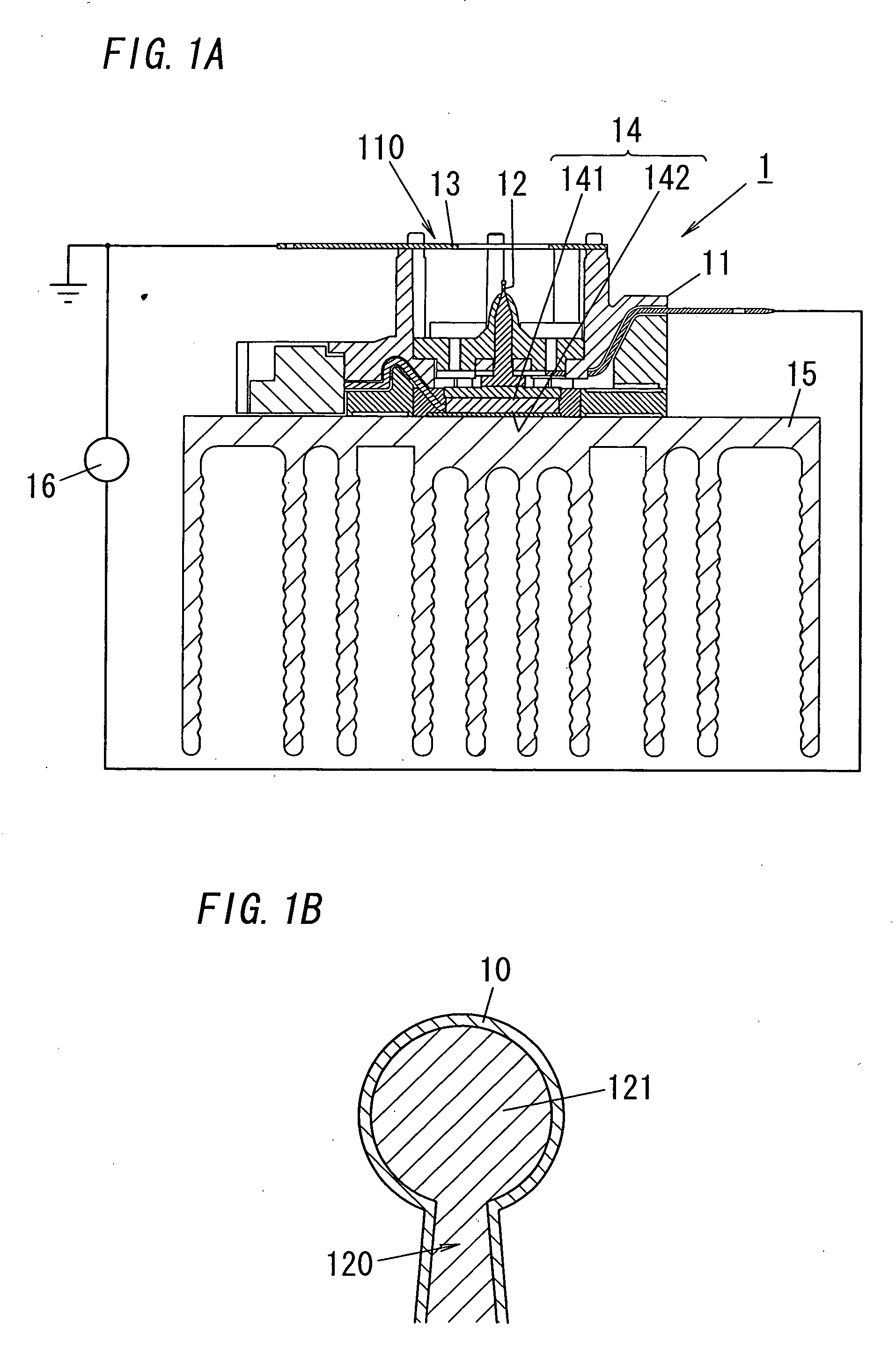
[0023]FIG. 1A is a sectional view of a first embodiment according to the present invention (i.e., an electrostatic atomizer 1), and FIG. 1B is a sectional view of the tip of a plug provided for the atomizer 1. The atomizer 1 comprises a housing 11, an electrostatic atomization pole 12, a counter electrode 13, a liquid supply mechanism 14, a radiator 15 and a power supply 16.

[0024]The housing 11 is formed of, for example, insulation material, and has a cavity 110. The electrostatic atomization pole 12 is a T-shaped electrode plug having a teardrop-shaped tip 121, and is inserted into and fixed at a hole of the bottom in the cavity 110 with the tip 121 forward along an axial direction of the cavity 110. The counter electrode 13 is located on the opening of the cavity 110 in front of the pole 12.

[0025]The liquid supply mechanism 14 is a Peltier device with a cooling portion 141 and a heat-radiating portion 142. The portions 141 and 142 are thermally connected to the base end of the ele...

second embodiment

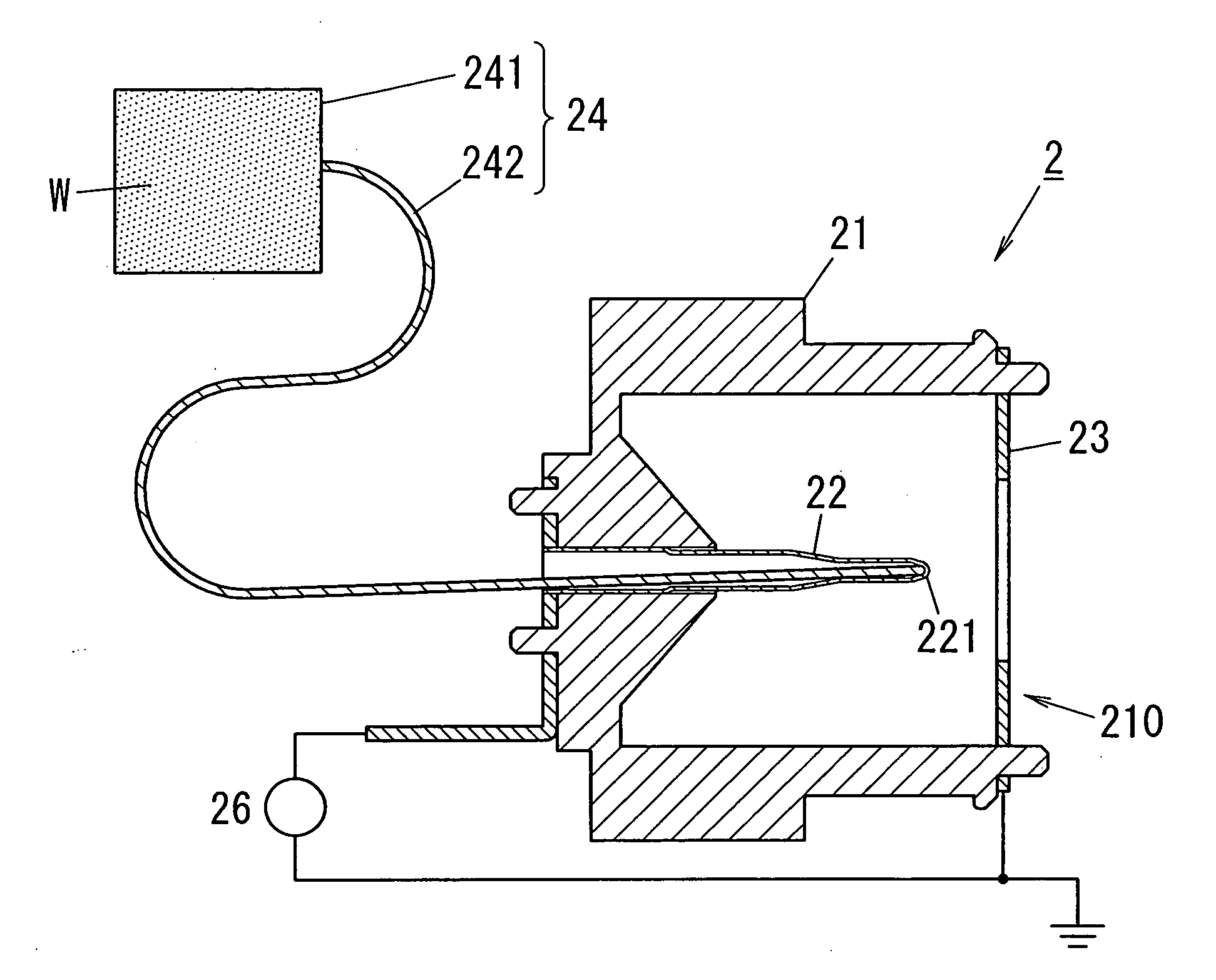
[0034]FIG. 6A is a sectional view of a second embodiment according to the present invention (i.e., an electrostatic atomizer 2), and FIG. 5B is a sectional view of the tip of a nozzle provided for the atomizer 2. The atomizer 2 comprises a housing 21, an electrostatic atomization pole 22, a counter electrode 23, a liquid supply mechanism 24 and a power supply 26.

[0035]The housing 21 is formed of, for example, insulation material, and has a cavity 210. The electrostatic atomization pole 22 is an arch-shaped hollow electrode nozzle having holes (221a, . . . ) at its tip 221, and is inserted into and fixed at a hole of the bottom in the cavity 210 with the tip 221 forward along an axial direction of the cavity 210. The counter electrode 23 is located on the opening of the cavity 210 in front of the pole 22.

[0036]The liquid supply mechanism 24 is formed of a liquid storage portion 241 for storing liquid (e.g., water W) and a liquid supply portion 242 for supplying the liquid into the po...

third embodiment

[0043]The second layer 30b and the third layer 30c are provided mainly to improve migration-proof, wearproof, acidproof and alkaliproof. That is, the layer 30b is an Au plating layer that is about 7 μm in thickness, and the layer 30c is an Au plating layer that is about 3 μm in thickness and contains added Co. The Au contained in the layers 30b and 30c has superior migration-proof, wearproof, acidproof, alkaliproof and productivity (barrel plating possible), and raises those characteristics of the pole 32. In order to prevent formation of pinhole defects, the thickness of the layer 30b is preferably equal to or more than 4 μm and more preferably about 7 μm including a margin. The Au plating layer containing Co, i.e., the layer 30c has high wettability, and also has hardness raised up to about Hv (Vickers Hardness) 250 from about Hv 80 to protect the layer 30c itself from flaw. Though the coating 30 may have one Au plating layer that contains added Co instead of the layers 30b and 30...


PUM


Abstract

An electrostatic atomizer equipped with an electrostatic atomization pole having superior migration-proof. The atomizer comprises the electrostatic atomization pole, a liquid supply mechanism that supplies the pole with liquid, and a power supply that supplies the pole with high voltage to electrostatically atomize the liquid held on the pole. A coating is formed on the surface of the pole, and the coating is formed of simple metal or alloy, which displays resistance to migration.

Description

TECHNICAL FIELD[0001]The invention relates generally to electrostatic atomizers and more particularly to an electrostatic atomizer that employs electrostatic atomization of water to generate mist of charged fine particles in the order of nanometer in size.BACKGROUND ART[0002]Such sort of electrostatic atomizer is seen in, for example, the patent document of Japanese Patent Number 3260150 (European Patent Publication Number 0 486 198 A1 or U.S. Pat. No. 5,337,963). A prior art device described in the document comprises a cartridge for storage of liquid suitable for electrostatic spraying, and a high voltage means for applying electrostatic potential to the liquid. The cartridge includes a capillary structure that extends into the interior of the cartridge so as to feed liquid by capillary action from the cartridge to a spraying outlet at a tip of the capillary structure. The cartridge also includes a means for providing an electrically conductive path to allow the application of an e...

Claims


Application Information

Patent Timeline
Patent Type & Authority Applications(United States)
IPC IPC(8): F23D11/32
CPCB05B5/0255B05B5/057B05B5/0533
Inventor NAKANO, SUMIAKISUGAWA, AKIHIDEHIRAI, TOSHIHISAHIRAI, KISHIKOMIHARA, FUMIOMATSUI, YASUNORI
Owner PANASONIC CORP
Features
  • R&D
  • Intellectual Property
  • Life Sciences
  • Materials
  • Tech Scout
  • Unparalleled Data Quality
  • Higher Quality Content
  • 60% Fewer Hallucinations
Learn More