Illumination system and illumination control method

a technology of illumination control and illumination system, which is applied in the direction of optical radiation measurement, lighting and heating apparatus, instruments, etc., can solve the problem that the color of an image cannot be displayed correctly, and achieve the effect of good illumination system performan

Active Publication Date: 2009-05-14
VISHAY CAPELLA MICROSYST TAIWAN LTD
View PDF2 Cites 51 Cited by
  • Summary
  • Abstract
  • Description
  • Claims
  • Application Information

AI Technical Summary

Benefits of technology

[0007]Therefore, it is one of objective of the present invention to provide an illumination system and an illumination control method to maintain good performance of the illumination system in different ambient lights environment for overcoming the foregoing drawbacks of the prior art.

Problems solved by technology

If a bulb having a lower color temperature is used in a room, and emits a slightly blue light, and the screen will show a slightly blue phenomenon, and thus the colors of an image cannot be displayed correctly.

Method used


Image

  • Illumination system and illumination control method
  • Illumination system and illumination control method
  • Illumination system and illumination control method

Examples


Embodiment Construction

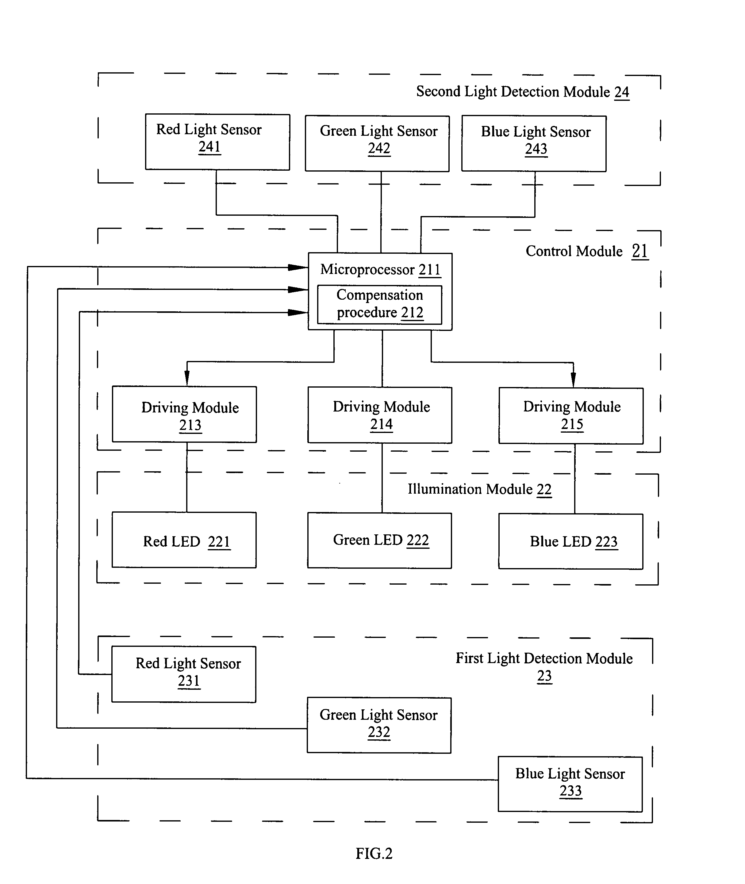
[0021]The description of an illumination system and an illumination method in accordance with a preferred embodiment of the present invention will be illustrated by the following figures. Please referring to FIG. 2 for a block diagram of a preferred embodiment of an illumination system in accordance with the present invention, the illumination system 2 comprises a control module 21, an illumination module 22, a first light detection module 23 and a second light detection module 24. The illumination module 22 comprises a red light emitting diode 221, a green light emitting diode 222 and a blue light emitting diode 223, for emitting different lights to be mixed into a desired light, and the control module 21 is provided for driving the illumination module 22 to emit light. In this embodiment, the control module 21 comprises a microprocessor 211 and three driving modules 213, 214, 215. The microprocessor 211 is provided for controlling the driving module to generate a driving signal to...


PUM


Abstract

This invention discloses an illumination method and an illumination control method. An embodiment of the illumination system includes two light detection modules for detecting a light produced by a light emitting diode and an ambient light, calculating a reference spectral distribution based on a detection result of the ambient light, comparing the detection result of the light emitting diode with the reference spectral distribution, and driving the illumination module to emit a light matching with the reference spectral distribution based on a comparison result. Another embodiment of the illumination system includes a light detection module for periodically switching the light emitting diode to emit light and stop emitting light. When the light emitting diode stops an illumination period, the light detection module detects an ambient light, and when the light emitting diode continues an illumination period, the light detection module detects a light produced by the light emitting diode.

Description

BACKGROUND OF THE INVENTION[0001]1. Field of the Invention[0002]The present invention relates to an illumination system and an illumination control method, and more particularly to a technical field of controlling a light emitting diode dynamically based on the detection of ambient light.[0003]2. Description of the Related Art[0004]Please referring to FIG. 1 for a block diagram of an illumination system in accordance with the prior art, the illumination system comprises a control module 11, an illumination module 12 and a light detection module 13. The illumination module 12 comprises a red light emitting diode 121, a green light emitting diode 122 and a blue light emitting diode 123. The control module 11 comprises a microprocessor 111 and three driving modules 113, 114, 115. The driving module 113, 114, 115 generate PWM signals to drive a red light emitting diode 121, a green light emitting diode 122 and a blue light emitting diode 123 to emit lights respectively. The light detect...

Claims


Application Information

Patent Timeline
Patent Type & Authority Applications(United States)
IPC IPC(8): H05B37/02G01J3/51
CPCG01J1/0488G01J1/1626G01J1/18G01J1/32Y02B20/46G01J1/4228H05B33/0857H05B33/0869H05B37/0218G01J1/4204H05B45/22Y02B20/40H05B45/20H05B47/11
Inventor SHIH, CHENG-CHUNG
Owner VISHAY CAPELLA MICROSYST TAIWAN LTD
Why Eureka
Try Eureka