Charge control apparatus, electrically powered vehicle and electric storage charge control method

Inactive Publication Date: 2009-05-14
TOYOTA JIDOSHA KK
View PDF2 Cites 65 Cited by
  • Summary
  • Abstract
  • Description
  • Claims
  • Application Information

AI Technical Summary

Benefits of technology

[0023]Further, by setting the control target of the voltage of DC power line to a voltage approximately the same as the crest value of the voltage of external power source, switching loss of the converter charging the electric storage by lowering the voltage from DC power line can

Problems solved by technology

In the electric motor drive and power processing apparatus, however, in order to realize a controlled battery charge with power factor of 1, single phase power source available for charging the battery is limited.
Specifically, the peak voltage (crest value) of the single phase power source for chargi

Method used


Image

  • Charge control apparatus, electrically powered vehicle and electric storage charge control method
  • Charge control apparatus, electrically powered vehicle and electric storage charge control method
  • Charge control apparatus, electrically powered vehicle and electric storage charge control method

Examples


Embodiment Construction

[0034]In the following, embodiments of the present invention will be described in detail with reference to the figures. Throughout the figures, the same or corresponding portions are denoted by the same reference characters and description thereof will not be repeated.

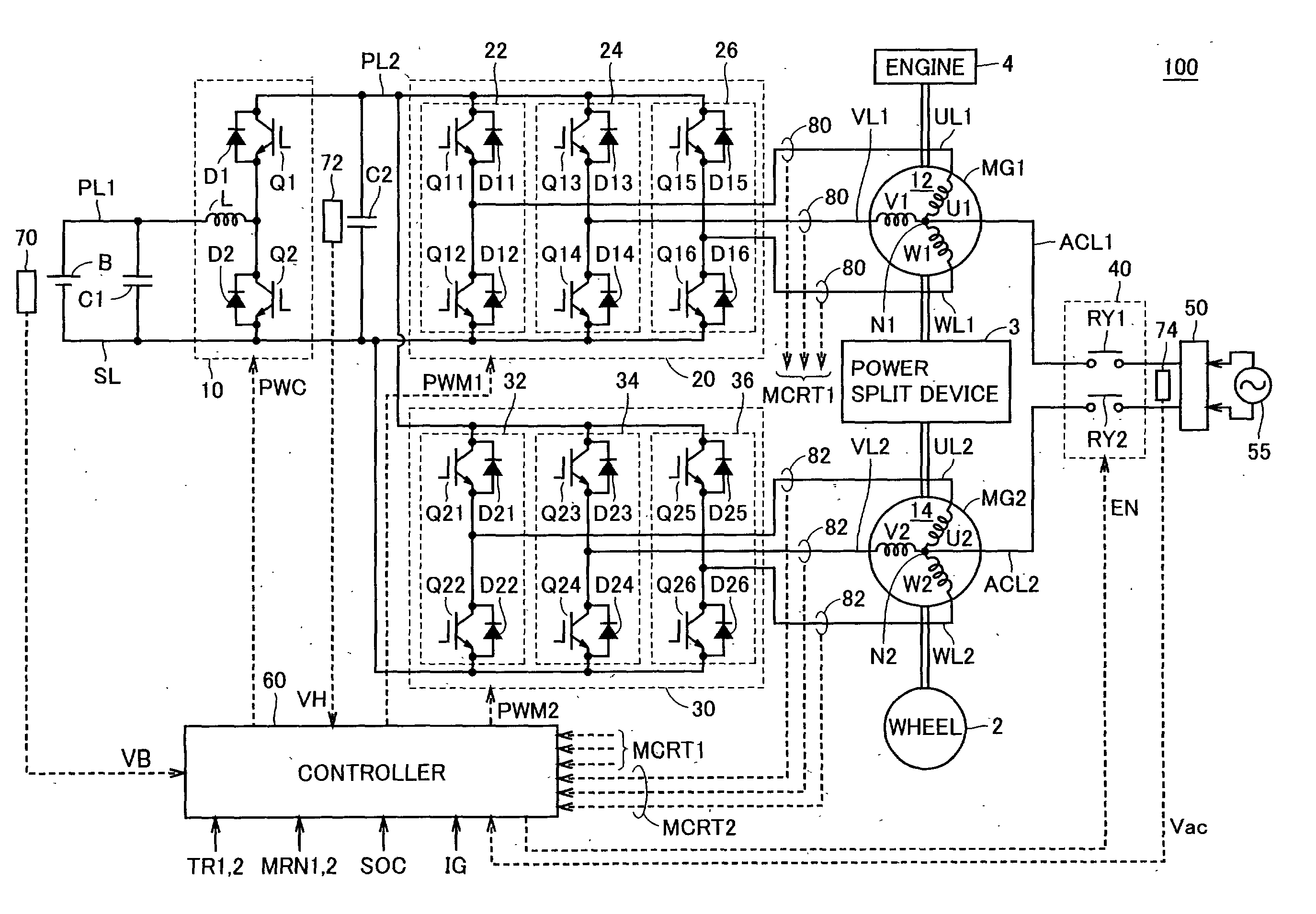
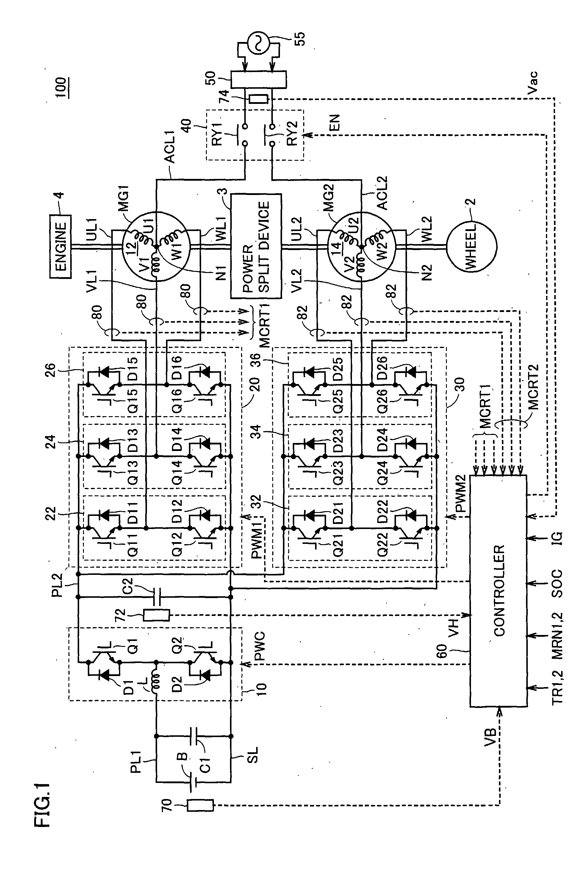
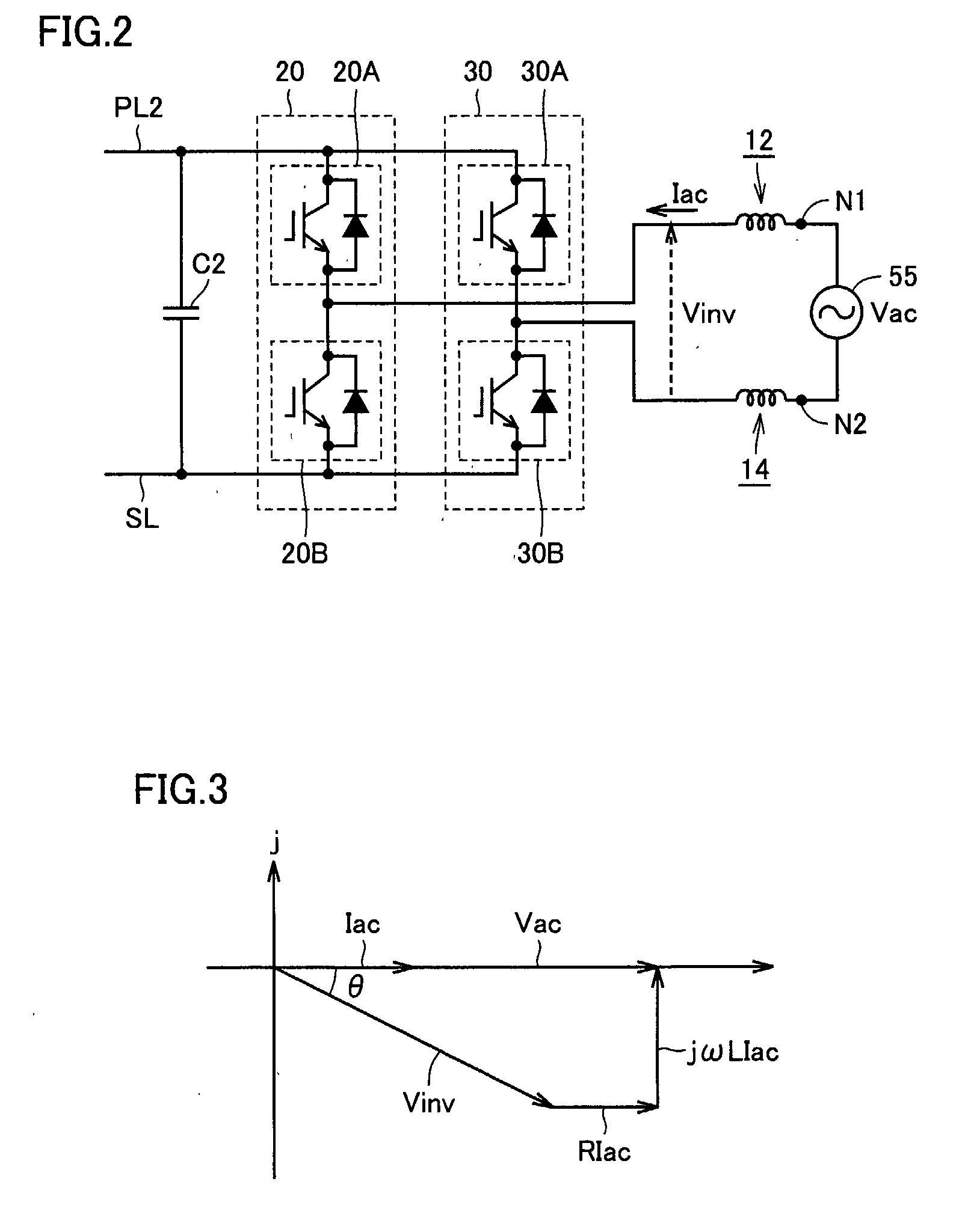
[0035]FIG. 1 is an overall block diagram of a hybrid vehicle shown as an example of the electrically powered vehicle in accordance with an embodiment of the present invention. Referring to FIG. 1, a hybrid vehicle 100 includes an engine 4, motor generators MG1 and MG2, a power split device 3 and wheels 2. Further, hybrid vehicle 100 includes an electric storage B, a boost converter 10, inverters 20 and 30, a controller 60, capacitors C1 and C2, power lines PL1 and PL2, a ground line SL, U-phase lines UL1 and UL2, V-phase lines VL1 and VL2, W-phase lines WL1 and WL2, voltage sensors 70 and 72, and current sensors 80 and 82. Hybrid vehicle 100 further includes power input lines ACL1 and ACL2, a relay circuit 40, an input...


PUM


Abstract

When it is determined that an electric storage is to be charged from a commercial power source, a controller sets a control target of a voltage of a power line to be controlled by a boost converter, based on a voltage of the commercial power source. Specifically, the controller sets the control target of the voltage to a level approximately equal to the crest value of voltage. Then, the controller outputs an input permission command to a relay circuit, and controls inverters to execute charging of the electric storage.

Description

TECHNICAL FIELD[0001]The present invention relates to a charge control apparatus and to an electrically powered vehicle. More specifically, the present invention relates to charge control of an electric storage mounted on an electrically powered vehicle such as an electric vehicle or a hybrid vehicle.BACKGROUND ART[0002]Japanese Patent Laying-Open No. 04-295202 discloses an electric motor drive and power processing apparatus used in an electrically powered vehicle. The electric motor drive and power processing apparatus includes a secondary battery, inverters IA and IB, induction motors MA and MB, and a control unit. Induction motors MA and MB respectively include Y-connected windings CA and CB, and to neutral points NA and NB of windings CA and CB, input / output ports are connected through an EMI filter.[0003]Inverters IA and IB are provided corresponding to induction motors MA and MB, respectively, and connected to windings CA and CB, respectively. Inverters IA and IB are connected...

Claims


Application Information

Patent Timeline
IPC IPC(8): B60L11/18H02J7/04B60L1/00H02J7/00
CPCB60K1/02Y02T10/6239B60K6/445B60L11/1803B60L11/1811B60L2210/14B60L2210/20H02J7/022Y02T10/6269Y02T10/7005Y02T10/7225Y02T10/725Y02T10/92Y02T90/127Y02T90/14B60K6/365Y02T10/7072B60L50/51B60L53/20H02J7/02H02J2207/20Y02T10/62Y02T10/72Y02T10/70B60Y2200/91B60Y2200/92Y02T90/12
Inventor OYOBE, HICHIROSAINAKAMURA, MAKOTOISHIKAWA, TETSUHIROYOSHIDA, HIROSHI
Owner TOYOTA JIDOSHA KK
Why Eureka
Try Eureka