System and Method for Current Measurement

a current measurement and system technology, applied in the field of information handling system circuits, can solve the problems of wasting power, reducing efficiency, and reducing the efficiency of current measurement, so as to reduce the cost of current measurement, improve efficiency, and reduce heat produced

Active Publication Date: 2009-05-14
DELL PROD LP
View PDF15 Cites 33 Cited by
  • Summary
  • Abstract
  • Description
  • Claims
  • Application Information

AI Technical Summary

Benefits of technology

[0010]The present invention provides a number of important technical advantages. One example of an important technical advantage is that current measurement becomes possible across virtually any resistance by monitoring the value of the resistance as current measurements are taken. This reduces the expense of current measurement by reducing or eliminating the need to add resistors to a circuit solely for the purpose of current measurement. Instead, existing resistance is used to measure current by monitoring the resistance value as current is measured. Avoiding the use of precision shunt resistors improves the efficiency with which information handling systems use power and reduce heat produced by information handling system operation. Further, avoiding the use of precision shunt resistors helps prevent the design of power systems having a single point of failure at the shunt resistor.

Problems solved by technology

Precise power management also presents a challenge in other information handling system applications, such as with hot-swap controllers.
However, Hall sensors are relatively expensive.
A difficulty with shunt resistors is that the voltage drop across the shunt resistor wastes power and produces heat as a byproduct of the current measurement.

Method used


Image

  • System and Method for Current Measurement
  • System and Method for Current Measurement
  • System and Method for Current Measurement

Examples


Embodiment Construction

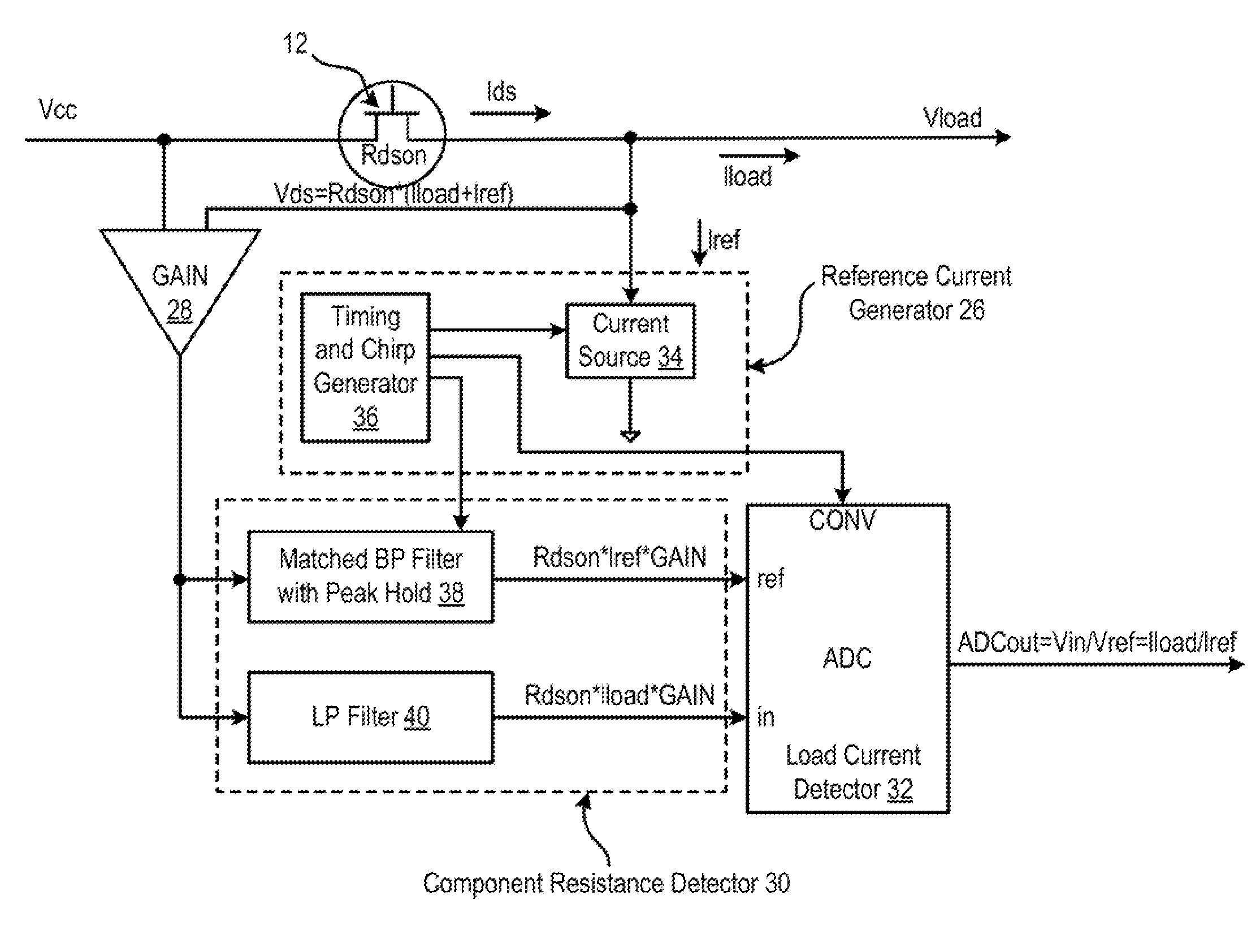
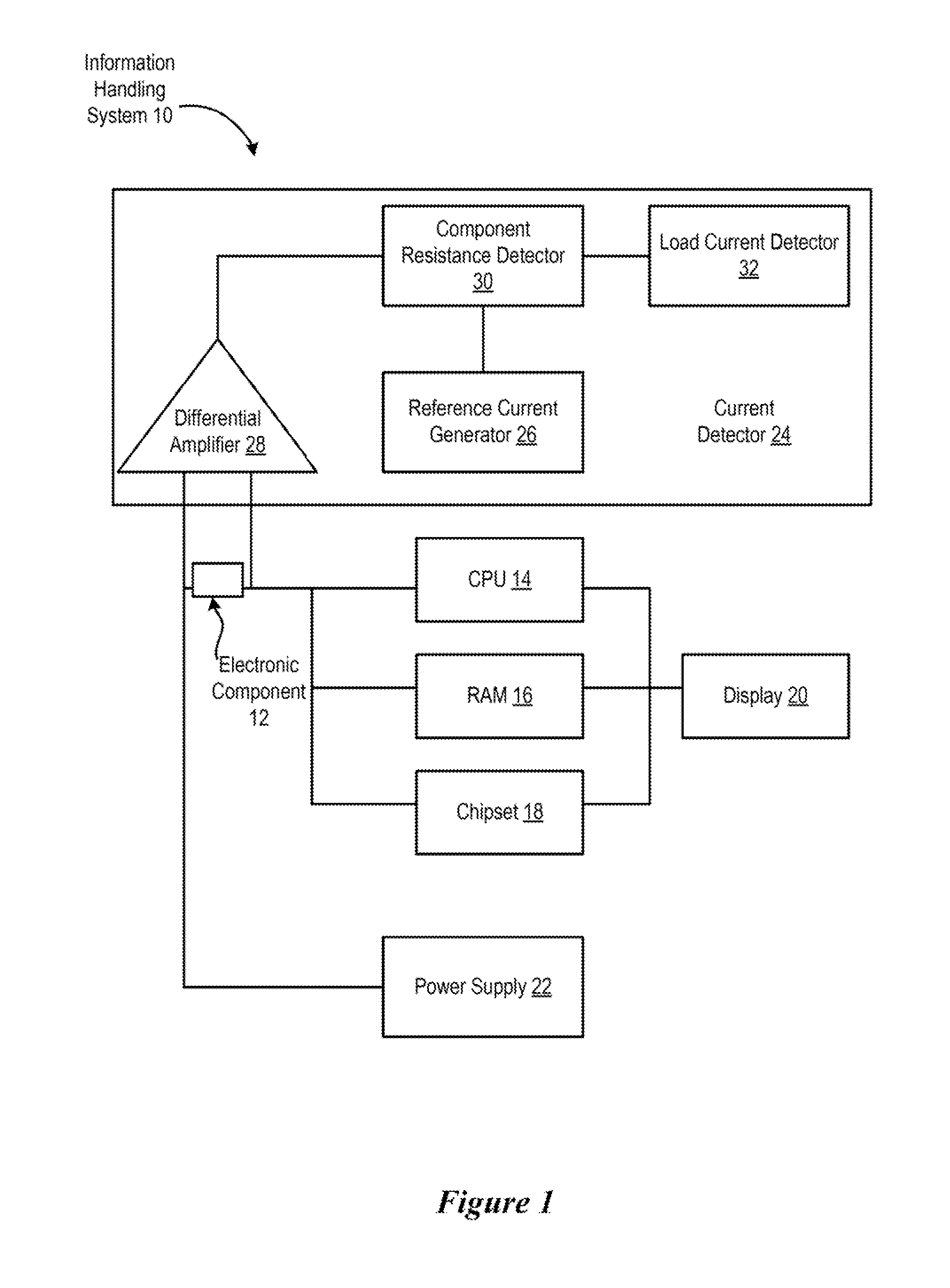
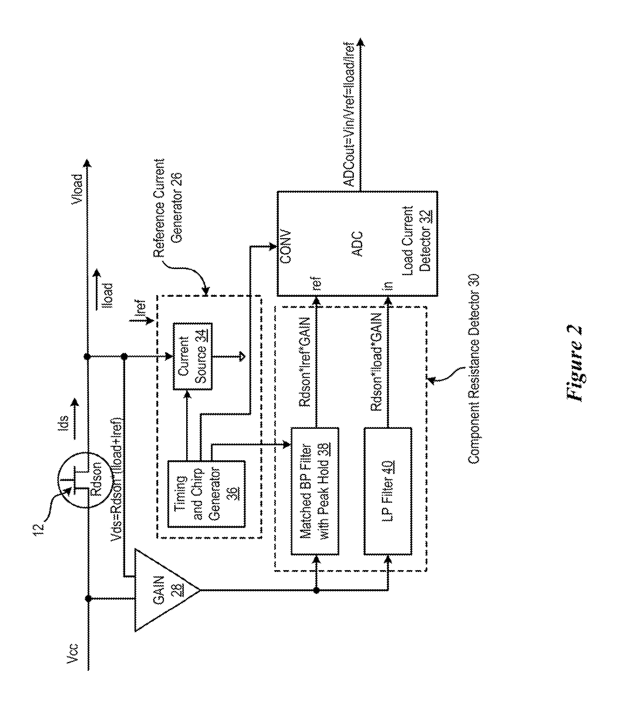
[0018]Load current across an information handling system circuit is determined by measuring resistance of a component in the circuit and voltage drop across the component. For purposes of this disclosure, an information handling system may include any instrumentality or aggregate of instrumentalities operable to compute, classify, process, transmit, receive, retrieve, originate, switch, store, display, manifest, detect, record, reproduce, handle, or utilize any form of information, intelligence, or data for business, scientific, control, or other purposes. For example, an information handling system may be a personal computer, a network storage device, or any other suitable device and may vary in size, shape, performance, functionality, and price. The information handling system may include random access memory (RAM), one or more processing resources such as a central processing unit (CPU) or hardware or software control logic, ROM, and / or other types of nonvolatile memory. Addition...


PUM


Abstract

Load current of a circuit is determined across a component of the circuit by calibrating the resistance of the component with a reference current having a distinguishable characteristic. For example, a reference current with swept frequency modulation is applied to the component so that the resistance of the component is determined from voltage drop associated with the reference current across the component. The component resistance is applied to a voltage drop associated with the load current to determine the load current. For example, a filter matched to the reference current frequency modulation isolates the reference current voltage drop so that a ratio of the reference current voltage drop and the load current voltage drop provides a ratio of the reference current and load current.

Description

BACKGROUND OF THE INVENTION[0001]1. Field of the Invention[0002]The present invention relates in general to the field of information handling system circuits, and more particularly to a system and method for current measurement.[0003]2. Description of the Related Art[0004]As the value and use of information continues to increase, individuals and businesses seek additional ways to process and store information. One option available to users is information handling systems. An information handling system generally processes, compiles, stores, and / or communicates information or data for business, personal, or other purposes thereby allowing users to take advantage of the value of the information. Because technology and information handling needs and requirements vary between different users or applications, information handling systems may also vary regarding what information is handled, how the information is handled, how much information is processed, stored, or communicated, and how...

Claims


Application Information

Patent Timeline
Patent Type & Authority Applications(United States)
IPC IPC(8): G01R27/14
CPCG01R19/0092
Inventor FARKAS, SANDOR
Owner DELL PROD LP
Why Eureka
Try Eureka