Laser radar apparatus that measures direction and distance of an object
a laser radar and distance measurement technology, applied in the direction of distance measurement, mirrors, instruments, etc., can solve the problems of large loss of beam splitting efficiency, inability to prevent diffusion of outgoing light, and downsizing of the apparatus, so as to improve the accuracy of detecting direction, improve beam splitting efficiency, and sacrifice the small size of the laser radar apparatus
- Summary
- Abstract
- Description
- Claims
- Application Information
AI Technical Summary
Benefits of technology
Problems solved by technology
Method used
Image
Examples
first embodiment
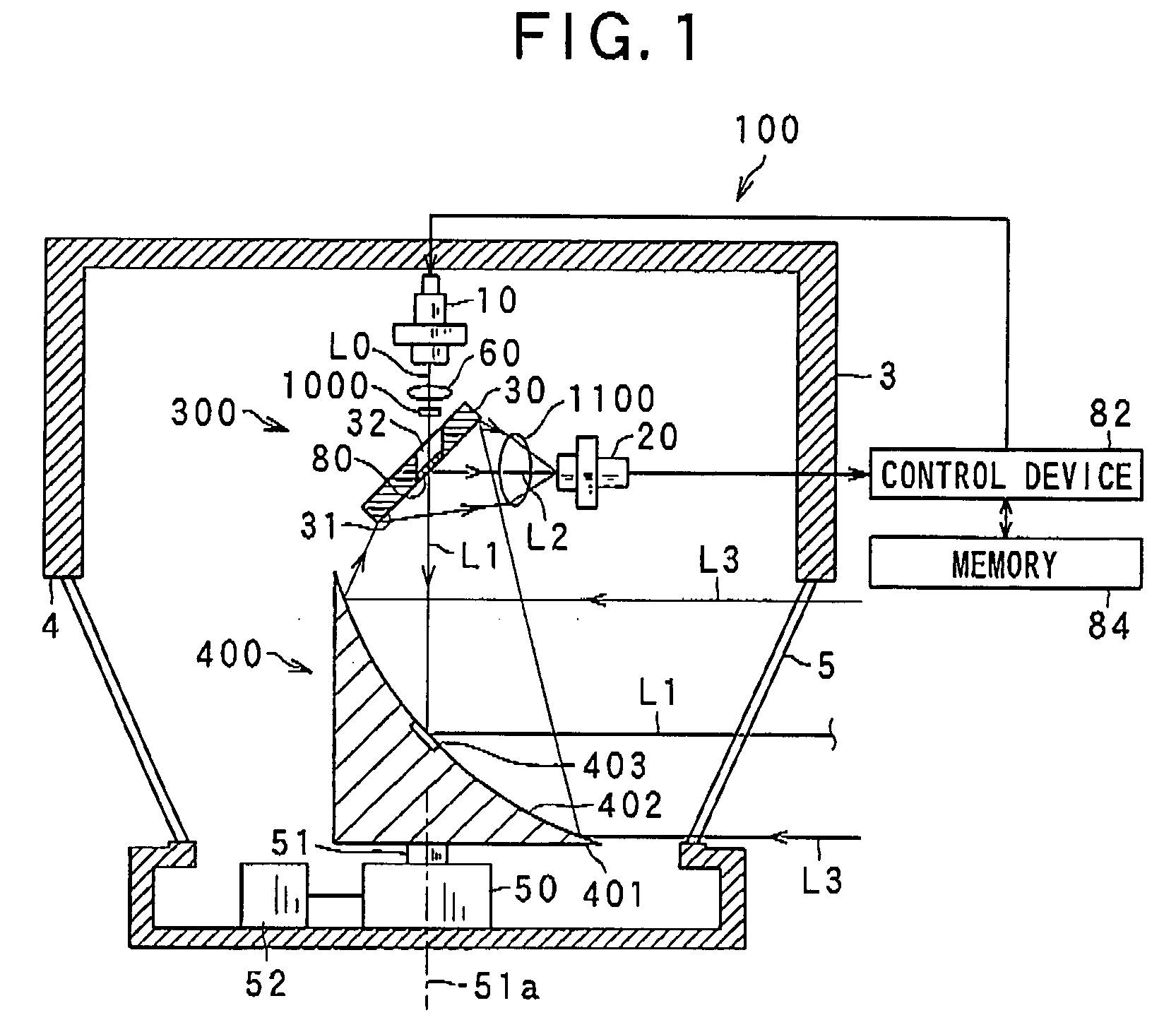
[0031]Referring to FIGS. 1-7, a laser radar apparatus according to a first embodiment of the present invention will be described.
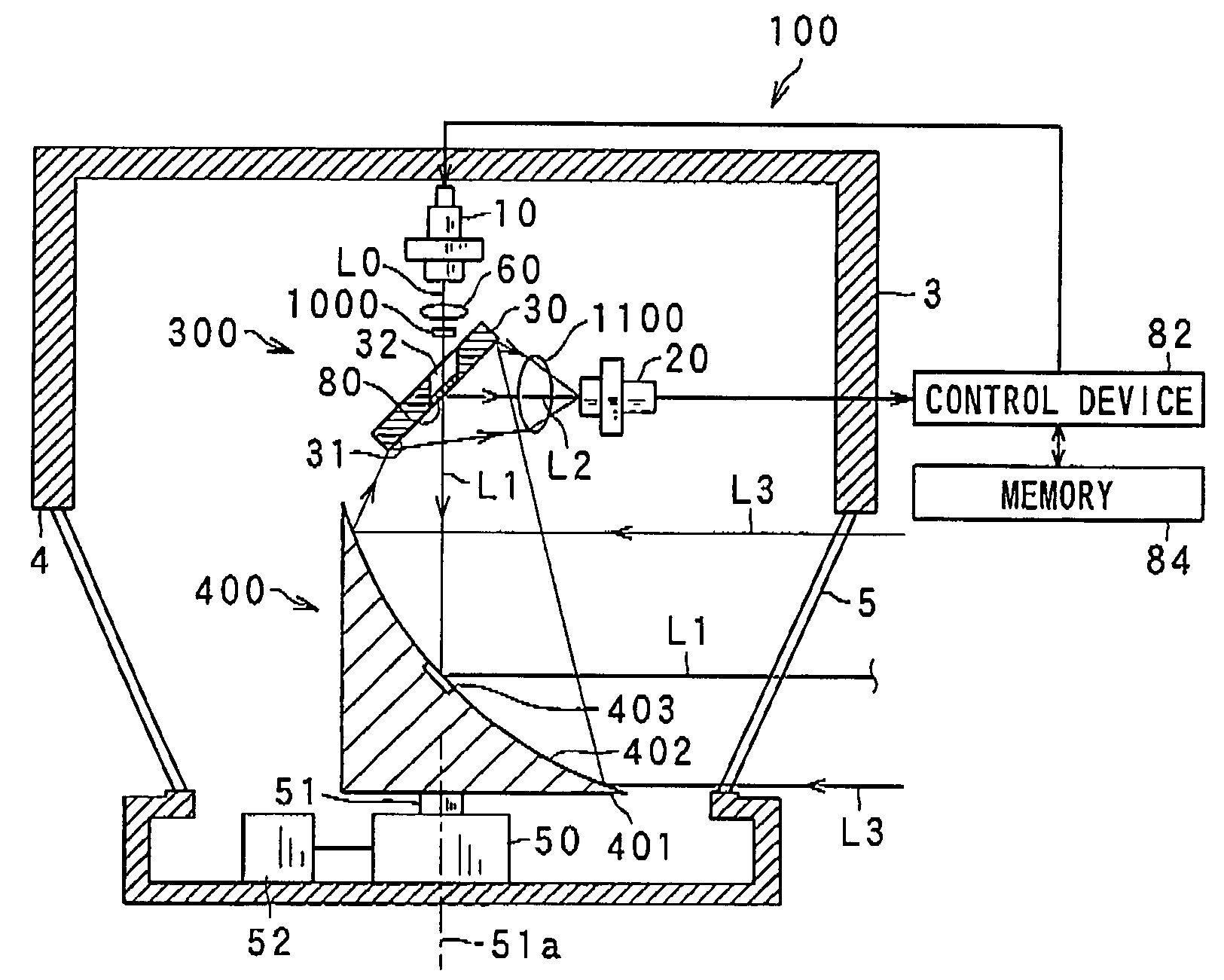
[0032]FIG. 1 is a schematic view of the laser radar apparatus 100 according to the first embodiment of the present invention.
[0033]As shown in FIG. 1, the laser radar apparatus 100 including a laser diode 10 and a photo diode 20 is designed to detect the direction to an object located in a measurement range, if it exists, and the distance of the object from the apparatus based on the difference of the phases of an outgoing light L0 emitted by the laser diode 10 and an incoming light L3 that is reflected back by the object and received by the photo diode 20, or the time of flight between the emission of an outgoing light L0 and reception of an incoming light L3 utilizing the speed of light. In this embodiment, the laser diode 10 emits a laser pulse.
[0034]The laser diode 10 emits a laser pulse having an axis thereof as an outgoing laser beam L0 into a measur...
second embodiment
[0112]Referring to FIGS. 9-11, a laser radar apparatus according to a second embodiment of the present invention will be described.
[0113]FIG. 9 is a schematic view of the laser radar apparatus 100B according to the second embodiment of the present invention.
[0114]In the present embodiment, the differences from the previous embodiment are based on the absence of the optical element 1000 between the laser diode 10 and the mirror 30 and the use of a rotating device 400A having a concave mirror 410. Thus, detailed discussion about the constituents of the laser radar apparatuses having the same function and the structure with those used in previous embodiments will be omitted.
[0115]As in the case of the first embodiment, the laser radar apparatus 100B is designed to detect the direction and the distance from the apparatus to an object based on the difference of the phases of outgoing light emitted by the laser diode 10 via the half-silvered mirror 80 and a flat mirror surface 411a, and i...
third embodiment
[0137]Referring to FIGS. 12-13, a laser radar apparatus according to a third embodiment of the present invention will be described.
[0138]FIG. 12 is a schematic view of the laser radar apparatus 100C according to the third embodiment of the present invention.
[0139]In the present embodiment, the differences from the second embodiment are based on the different structure of a rotary device 400B from the rotary device 400B because the rotary device 400B includes a concave mirror 420 that is different from the concave mirror 410. Thus, the detailed discussion about the constituents of the laser radar apparatuses having the same function and the structure with those used in the previous embodiments will be omitted.
[0140]The laser radar apparatus 100C has a rotary device 400B having a concave mirror 420. The concave mirror 420 has a concave reflecting portion 402 that has the concave-shaped mirror surface 402a and a flat reflecting portion 421 that has a flat mirror surface 421a. The refle...
PUM
 Abstract
Description
Claims
Application Information
 - R&D
- Intellectual Property
- Life Sciences
- Materials
- Tech Scout
- Unparalleled Data Quality
- Higher Quality Content
- 60% Fewer Hallucinations
Browse by: Latest US Patents, China's latest patents, Technical Efficacy Thesaurus, Application Domain, Technology Topic, Popular Technical Reports.
© 2025 PatSnap. All rights reserved.Legal|Privacy policy|Modern Slavery Act Transparency Statement|Sitemap|About US| Contact US: help@patsnap.com


