Turbine Blade Tip Cooling System

a cooling system and turbine blade technology, applied in the field of turbine blades, can solve the problems of reducing the useful life of the turbine blade, the likelihood of failure, and localized hot spots, and achieve the effect of facilitating the cooling of the blade tip

Active Publication Date: 2009-05-14
SIEMENS ENERGY INC
View PDF24 Cites 7 Cited by
  • Summary
  • Abstract
  • Description
  • Claims
  • Application Information

AI Technical Summary

Benefits of technology

[0004]This invention relates to a turbine blade cooling system for turbine blades used in turbine engines. In particular, the turbine blade cooling system includes a cavity positioned between two or more walls forming a housing of the turbine blade. The cooling system may include at least one elongated tip cooling chamber forming a portion of the cooling system and at least partially defined by a tip wall proximate to the first end. An inner surface of the tip wall may include a plurality of curved bumper protrusions extending from the inner surface radially inward toward the root. Recessed tip slots may be positioned between the protrusions, which reduces the thickness of the outer wall at the first end, thereby making it easier to cool the tip of the blade.

Problems solved by technology

In addition, turbine blades often contain cooling systems for prolonging the life of the blades and reducing the likelihood of failure as a result of excessive temperatures.
However, centrifugal forces and air flow at boundary layers often prevent some areas of the turbine blade from being adequately cooled, which results in the formation of localized hot spots.
Localized hot spots, depending on their location, can reduce the useful life of a turbine blade and can damage a turbine blade to an extent necessitating replacement of the blade.

Method used


Image

  • Turbine Blade Tip Cooling System
  • Turbine Blade Tip Cooling System
  • Turbine Blade Tip Cooling System

Examples


Embodiment Construction

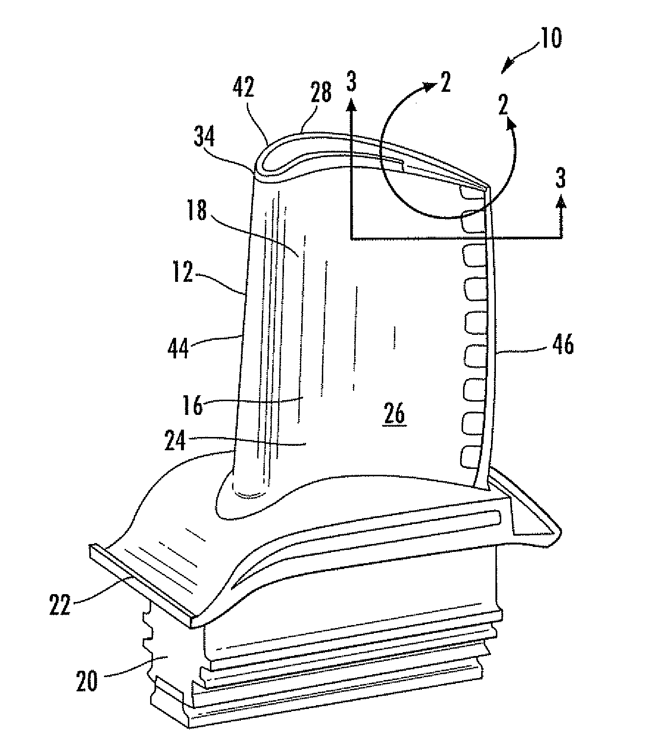
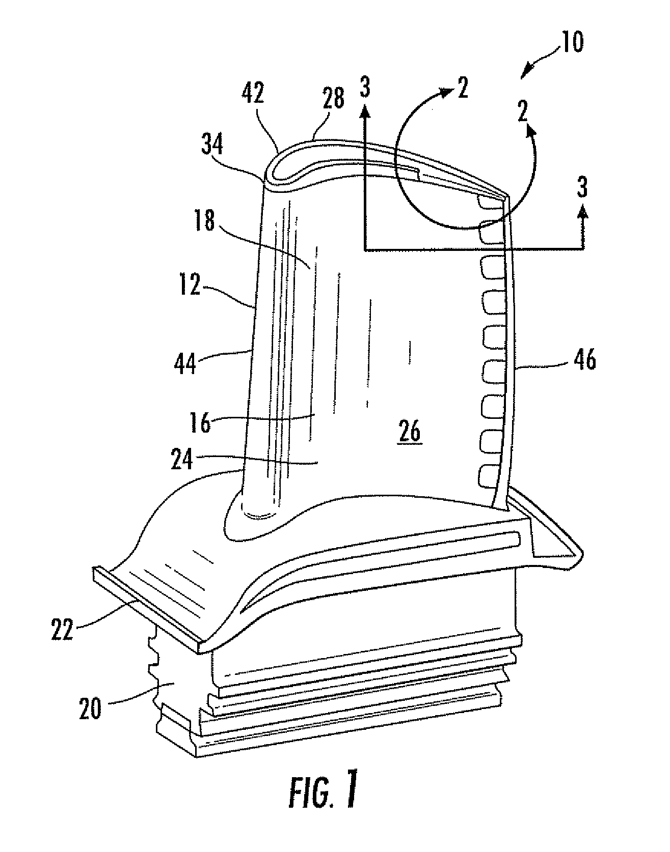
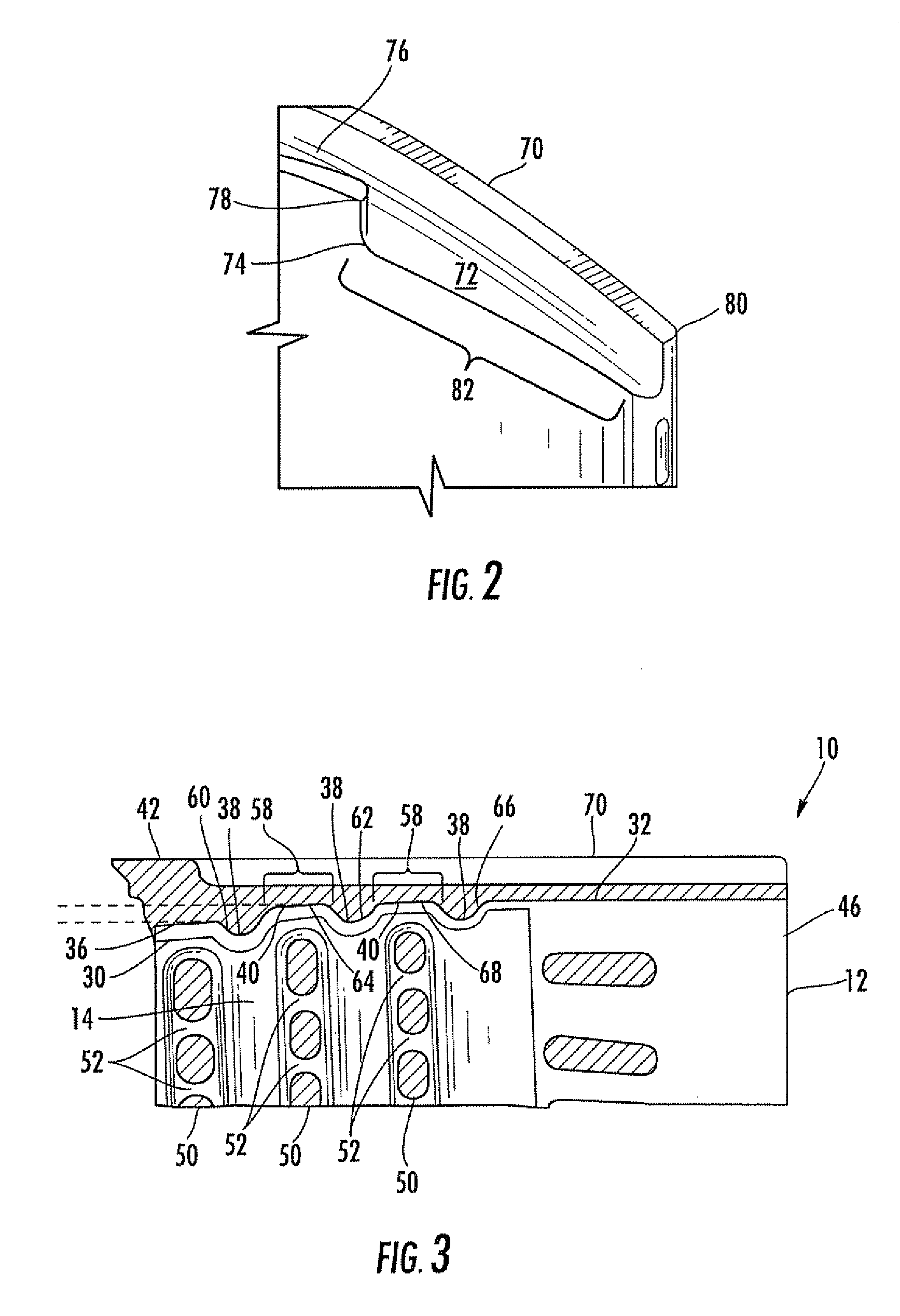
[0017]As shown in FIGS. 1-3, this invention is directed to a turbine blade cooling system 10 for turbine blades 12 used in turbine engines. In particular, the turbine blade cooling system 10 includes a cavity 14, as shown in FIGS. 2 and 3, positioned between two or more walls forming a housing 16 of the turbine blade 12. The cooling system 10 may include at least one elongated tip cooling chamber 30 forming a portion of the cooling system 10 and at least partially defined by a tip wall 32 proximate to the first end 34. An inner surface 36 of the tip wall 32 may include a plurality of curved bumper protrusions 38 extending from the inner surface 36 radially inward toward the root 20. Recessed tip slots 40 may be positioned between the protrusions 38, which reduces the thickness of the outer wall 24 at the first end 34, thereby making it easier to cool the tip 42 of the blade 12.

[0018]As shown in FIG. 1, the turbine blade 12 may be formed from a generally elongated blade 18 coupled to...


PUM


Abstract

A turbine blade for a turbine engine having a cooling system in the turbine blade formed from at least one elongated tip cooling chamber forming a portion of the cooling system and at least partially defined by the tip wall proximate to the first end. An inner surface of the tip wall may include a plurality of curved bumper protrusions extending from the inner surface radially inward toward the root. The cooling system may include a plurality of ribs generally aligned with the trailing edge, and the curved bumper protrusions may be offset in a chordwise direction relative to the ribs. A throat section may extend between a first forwardmost curved bumper protrusion and a second immediately adjacent downstream curved bumper protrusion and may be offset radially outward from an inner tip surface, thereby creating a first recessed tip slot with a reduced tip wall thickness.

Description

FIELD OF THE INVENTION[0001]This invention is directed generally to turbine blades, and more particularly to cooling systems in hollow turbine blades.BACKGROUND[0002]Typically, gas turbine engines include a compressor for compressing air, a combustor for mixing the compressed air with fuel and igniting the mixture, and a turbine blade assembly for producing power. Combustors often operate at high temperatures that may exceed 2,500 degrees Fahrenheit. Typical turbine combustor configurations expose turbine blade assemblies to these high temperatures. As a result, turbine blades must be made of materials capable of withstanding such high temperatures. In addition, turbine blades often contain cooling systems for prolonging the life of the blades and reducing the likelihood of failure as a result of excessive temperatures.[0003]Typically, turbine blades are formed from a root portion at one end and an elongated portion forming a blade that extends outwardly from a platform coupled to t...

Claims


Application Information

Patent Timeline
Patent Type & Authority Applications(United States)
IPC IPC(8): F01D5/18F01D5/08
CPCF01D5/187F01D5/20F05D2230/21F05D2240/127F05D2250/71F05D2260/2212F05D2250/611
Inventor GU, XUBINLIANG, GEORGE
Owner SIEMENS ENERGY INC
Why Eureka
Try Eureka