Catalytic Combustor And Method Thereof
a combustor and catalyst technology, applied in the direction of combustion process, combustion ignition, lighting and heating apparatus, etc., can solve the problems of fuel evaporation, risk of thermal degradation of catalysts, and few, if any, commercial applications
- Summary
- Abstract
- Description
- Claims
- Application Information
AI Technical Summary
Benefits of technology
Problems solved by technology
Method used
Image
Examples
Embodiment Construction
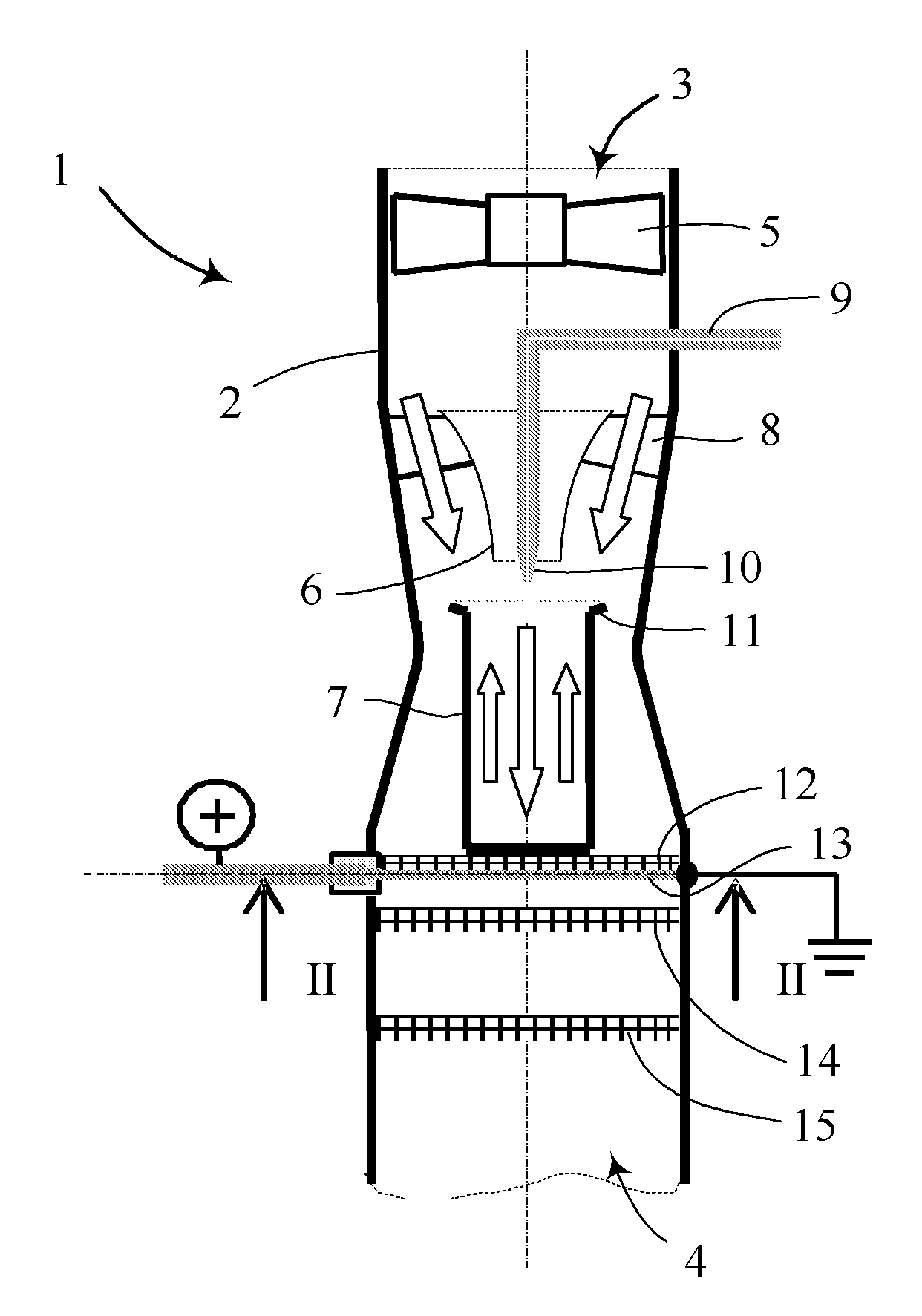
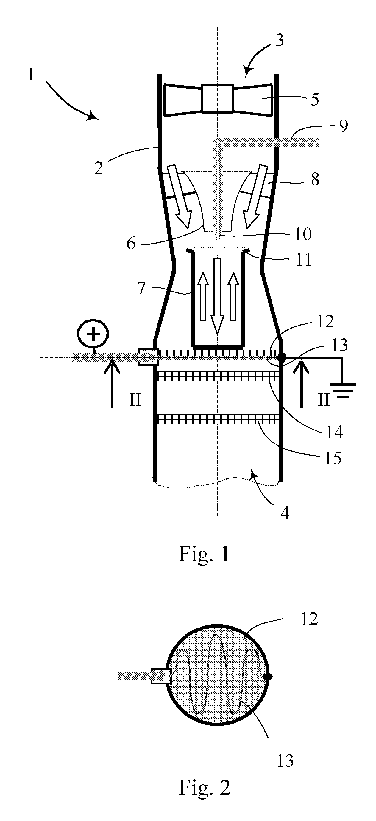
[0008]A catalytic combustor 1 is shown in section in FIG. 1. The combustor comprises a generally cylindrical outer housing 2, forming a venturi in the mid-section, and the housing has an inlet 3 at one end and an outlet 4 at the other end. A fan 5 is provided at the inlet 3, for supplying the combustor 1 with air, and the air is partly directed into a gradually contracted channel 6, leading to a fuel-evaporating device 7. Another part of the airflow is led outside the channel 6, where the air passes swirl vanes 8, located at an inlet to the venturi. A fuel supply pipe 9 enters the housing upstream of the channel 6, and the pipe is provided with a nozzle 10, which can be a simple orifice, for injecting liquid fuel from just below or inside the channel 6 and into the fuel-evaporating device 7. The nozzle 10 is located in the middle of the airflow running through the channel 6. The fuel-evaporating device 7 is equipped with an outwardly extending edge 11 at its upper perimeter, where t...
PUM
 Abstract
Description
Claims
Application Information
 - R&D
- Intellectual Property
- Life Sciences
- Materials
- Tech Scout
- Unparalleled Data Quality
- Higher Quality Content
- 60% Fewer Hallucinations
Browse by: Latest US Patents, China's latest patents, Technical Efficacy Thesaurus, Application Domain, Technology Topic, Popular Technical Reports.
© 2025 PatSnap. All rights reserved.Legal|Privacy policy|Modern Slavery Act Transparency Statement|Sitemap|About US| Contact US: help@patsnap.com


