Methods for coupling an RFID chip to an antenna

Active Publication Date: 2009-05-21
RADIOFIDO
View PDF6 Cites 16 Cited by
  • Summary
  • Abstract
  • Description
  • Claims
  • Application Information

AI Technical Summary

Benefits of technology

[0033]The first method uses an interdigitated antenna feed that presents a large number of positions for a randomly oriented microradio to connect to, thus increasing the likelihood of a good connection across an antenna feed point gap. In one embodiment the microradio is provided with dual-sided or 3D bonding pads, integrated onto the RFID chip (as opposed to 2D pads) to allow placement of the chip on the antenna and connection to its feed point regardless of orientation and position of the microradio chip. Note, the chip is made for direct connection to the feed region of, for example, a spiral, dipole, or loop antenna. For quick and inexpensive placement of the chip, the chip can be carried in a slurry that is deposited over the interdigitated gap for the antenna feed, where the gap is made the same size as the length of the chip, i.e., separation between the two pads on the chip. Chip and interfinger dimensions can be made quite small to permit the IC cost savings associated with microradio chips. This placement method is probabilistic in that there is a high probability that one microradio will be properly connected across at least one gap in the interdigitized antenna feed due to its many tines and its interdigitated design.
[0034]When the interdigitated structure is formed utilizing conductive ink, the resistivity of the ink can sometimes cause problems. In order to increase the conductivity and decrease the resistance, after a microradio is deposited across the tines of the interdigitated structure, a conductive adhesive and / or solder can be deposited over the tines to either side of the tines across which the microradio is connected. This substantially increases the line width of the tines to eliminate the above-mentioned problems with the resistivity of the conductive ink.
[0045]Alternatively, instead of imaging a previous interdigitated metallized feed region of the antenna, an alternative would be to leave the feed region on the antenna un-metallized and let the stamping process from the photoconductor simultaneously define the interdigitated tines and also apply the RFID chip. This would avoid precise mechanical orientation issues.

Problems solved by technology

When the interdigitated structure is formed utilizing conductive ink, the resistivity of the ink can sometimes cause problems.

Method used


Image

  • Methods for coupling an RFID chip to an antenna
  • Methods for coupling an RFID chip to an antenna
  • Methods for coupling an RFID chip to an antenna

Examples


Embodiment Construction

[0067]By way of further background, RFID tags are becoming a well-established method for tracking materials during shipping and storage. In many applications they replace the printed bar code labels on items because they do not require a close proximity for the automatic reader. RFID tags that conform to the ISO / IEC 18000 standard also can contain significantly more data than a printed bar code label and can be modified en route to include waypoint or other information.

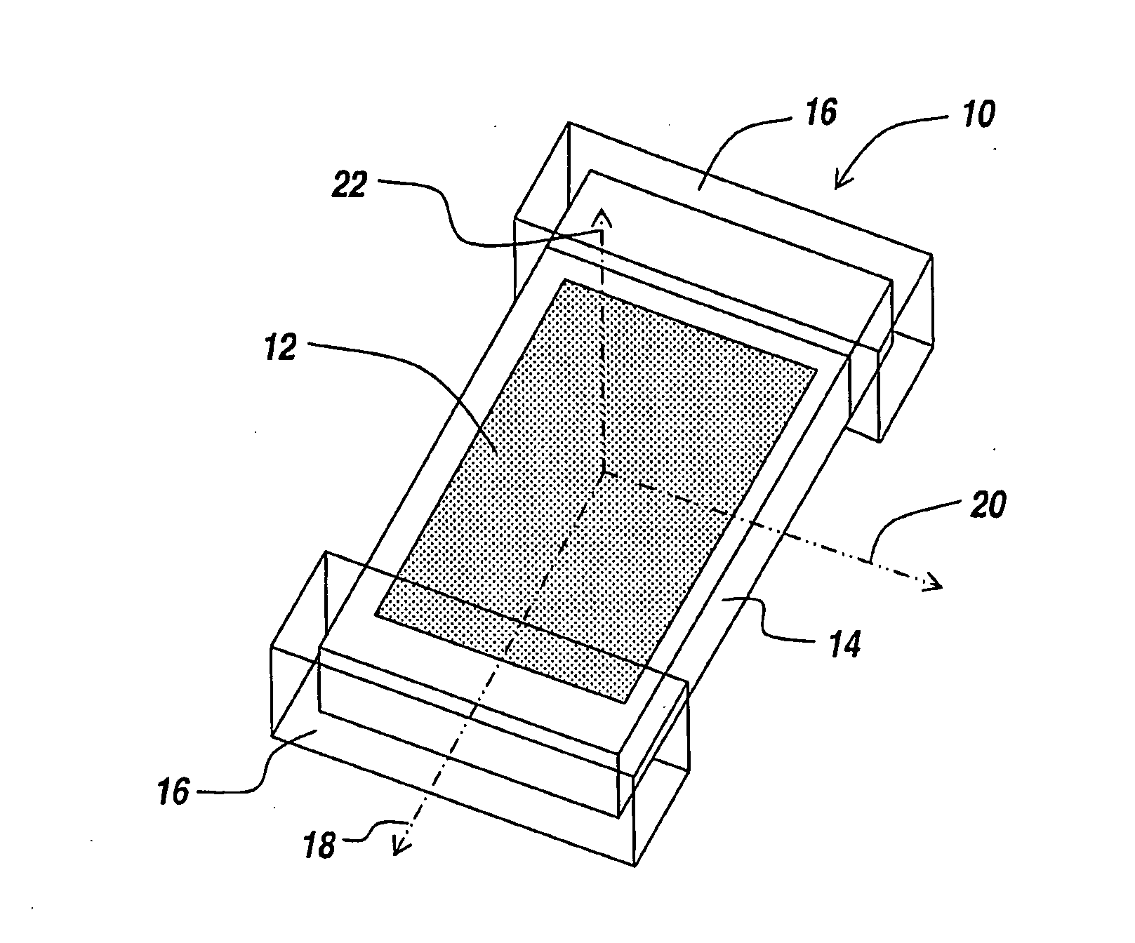
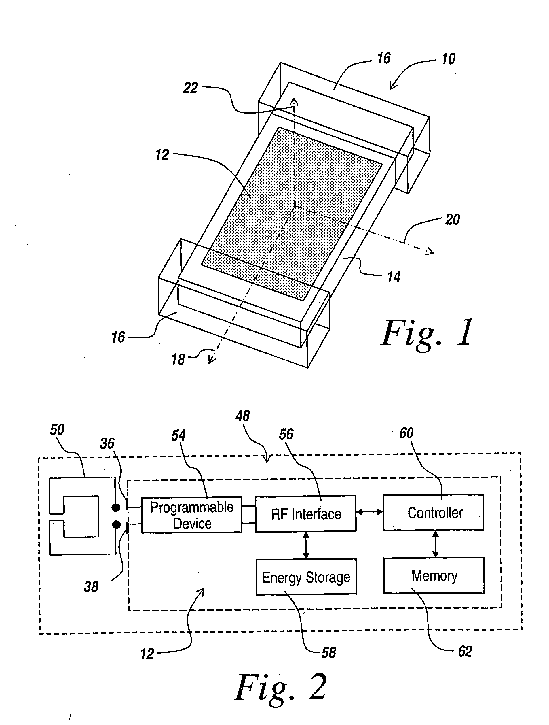
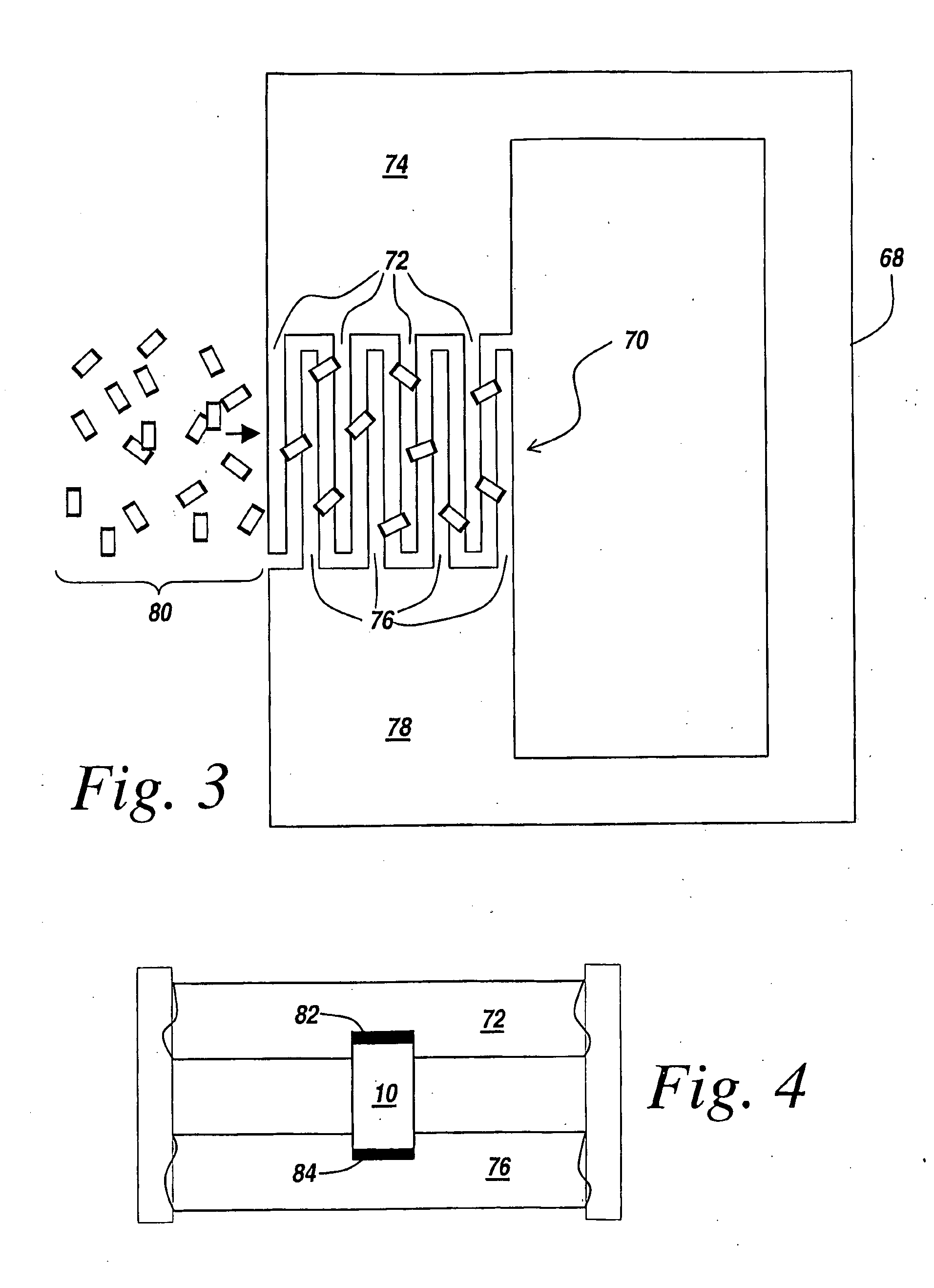
[0068]Present RFID tags cost about $US 0.50 (50 cents) and are usually fabricated by electrically bonding a custom integrated circuit (IC) to a substrate containing a printed circuit antenna. The usual fabrication method, well known in the electronics industry is flip-chip bonding. An electrically conductive solder paste is applied to the appropriate places on the antenna. A “pick and place” machine picks up the IC die and places it onto the substrate in the proper location with respect to the antenna connections. The...


PUM


Abstract

A method for mounting multiple small RFID chips onto larger antenna. The chips are mechanically aligned with an interdigitated gap at the feed point of the antenna by electrostatic or magnetic techniques. In an alternate embodiment RF field coupling between the chips and the antenna is employed.

Description

RELATED APPLICATIONS[0001]This Application claims rights under 35 USC § 119(e) from U.S. Application Ser. No. 60 / 711,218 filed Aug. 25, 2005, the contents of which are incorporated herein by reference.FIELD OF THE INVENTION[0002]This invention relates to the use of Radio Frequency Identification (RFID) tags for tracking items during shipping, receiving the items at final destination and inventory control of items, and more specifically to methods for mounting the RFID chip onto a larger antenna.BACKGROUND OF THE INVENTION[0003]RFID tags have been utilized extensively to be able to trace pallets from a point of shipment through a destination, with the RFID tags being passive devices that are read out with RF energy, usually in the 900 MHz range. These passive devices are parasitically powered by the energy impinging upon the antenna of the tag that powers the integrated circuits within the tag, with the result that the tag transmits the identity of the pallet in response to a probing...

Claims


Application Information

Patent Timeline
Patent Type & Authority Applications(United States)
IPC IPC(8): H04Q5/22
CPCG06K19/07756G06K19/07749
Inventor ROSSMAN, COURT E
Owner RADIOFIDO
Why Eureka
Try Eureka