Drive force output apparatus, method for controlling same apparatus, and vehicle

a technology of output apparatus and output power, which is applied in the direction of motor/generator/converter stopper, dynamo-electric converter control, instruments, etc., can solve the problems of limiting the power of the auxiliary in such a case, the difficulty of properly monitoring and controlling the soc level of the battery, and the failure of the output power of the output apparatus to achieve the effect of reliable power for driving an electric motor

Inactive Publication Date: 2009-05-21
TOYOTA JIDOSHA KK
View PDF3 Cites 53 Cited by
  • Summary
  • Abstract
  • Description
  • Claims
  • Application Information

AI Technical Summary

Benefits of technology

[0009]The invention relates to a drive force output apparatus, a method for controlling the same apparatus, and a vehicle, which more properly monitor and control the amount of power stored in a power storage and thus more reliably secure power for driving an electric motor.
[0011]According to the drive force output apparatus of the first aspect of the invention, as described above, the reference power storage amount corresponding to the reference of the range within which the power storage amount of the power storage is monitored is set based on at least one of the state of operation by the operator and the state of the drive force output apparatus, and the maximum auxiliary power representing the upper limit of power allowed to be consumed by the auxiliary is set based on the set reference power storage amount, and the power storage amount of the power storage is monitored based on the reference power storage amount, and the power generator, the electric motor, and the auxiliary are controlled such that drive force corresponding to the target drive force is output to the drive shaft while the power consumed by the auxiliary remains equal to or smaller than the maximum auxiliary power. As such, because the power storage amount of the power storage is monitored based on the reference power storage amount that is set based on the state of operation by the operator and / or the state of the drive force output apparatus, the power storage amount of the power storage can be monitored and controlled more properly. Further, because the power consumed by the auxiliary is kept equal to or smaller than the maximum auxiliary power, the power consumed by the auxiliary is limited based on the state of operation by the operator and / or the state of the drive force output apparatus, and power for driving the electric motor can be more reliably secured. Certainly, drive force corresponding the target drive force can be properly output to the drive shaft.
[0013]Incorporating the drive force output apparatus of the first aspect of the invention, the vehicle of the second aspect of the invention provides the same advantages and effects as those of the drive force output apparatus of the first aspect of the invention, such as the aforementioned capability of monitoring and controlling the power storage amount of the power storage more properly and the aforementioned capability of securing power for driving the electric motor more reliably.
[0015]According to the control method of the third aspect of the invention, as described above, the reference power storage amount corresponding to the reference of the range within which the power storage amount of the power storage is monitored is set based on at least one of the state of operation by the operator and the state of the drive force output apparatus, and the maximum auxiliary power representing the upper limit of power allowed to be consumed by the auxiliary is set based on the set reference power storage amount, and the power storage amount of the power storage is monitored based on the reference power storage amount, and the power generator, the electric motor, and the auxiliary are controlled such that drive force corresponding to the target drive force is output to the drive shaft while the power consumed by the auxiliary remains equal to or smaller than the maximum auxiliary power. As such, because the power storage amount of the power storage is monitored based on the reference power storage amount that is set based on the state of operation by the operator and / or the state of the drive force output apparatus, the power storage amount of the power storage can be monitored and controlled more properly. Further, because the power consumed by the auxiliary is kept equal to or smaller than the maximum auxiliary power, the power consumed by the auxiliary is limited based on the state of operation by the operator and / or the state of the drive force output apparatus, and power for driving the electric motor can be more reliably secured. Certainly, drive force corresponding the target drive force can be properly output to the drive shaft.

Problems solved by technology

In general, drive force output apparatuses of this kind involve a difficulty in properly monitoring and controlling the SOC level of the battery.
However, how to limit the power for the auxiliary in such a case is still a pending issue.

Method used


Image

  • Drive force output apparatus, method for controlling same apparatus, and vehicle
  • Drive force output apparatus, method for controlling same apparatus, and vehicle
  • Drive force output apparatus, method for controlling same apparatus, and vehicle

Examples


Embodiment Construction

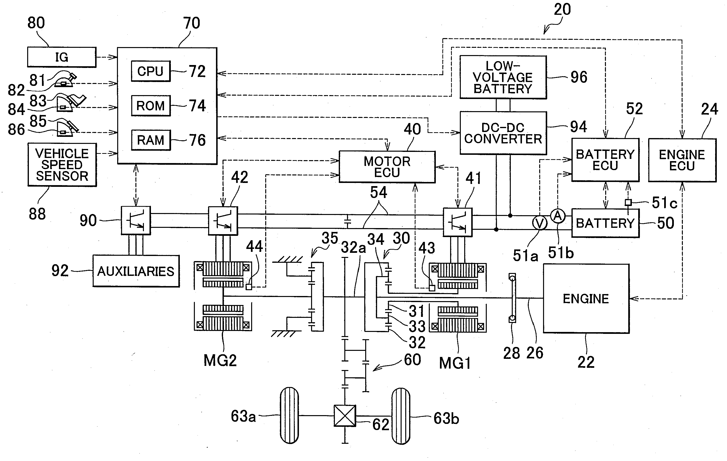
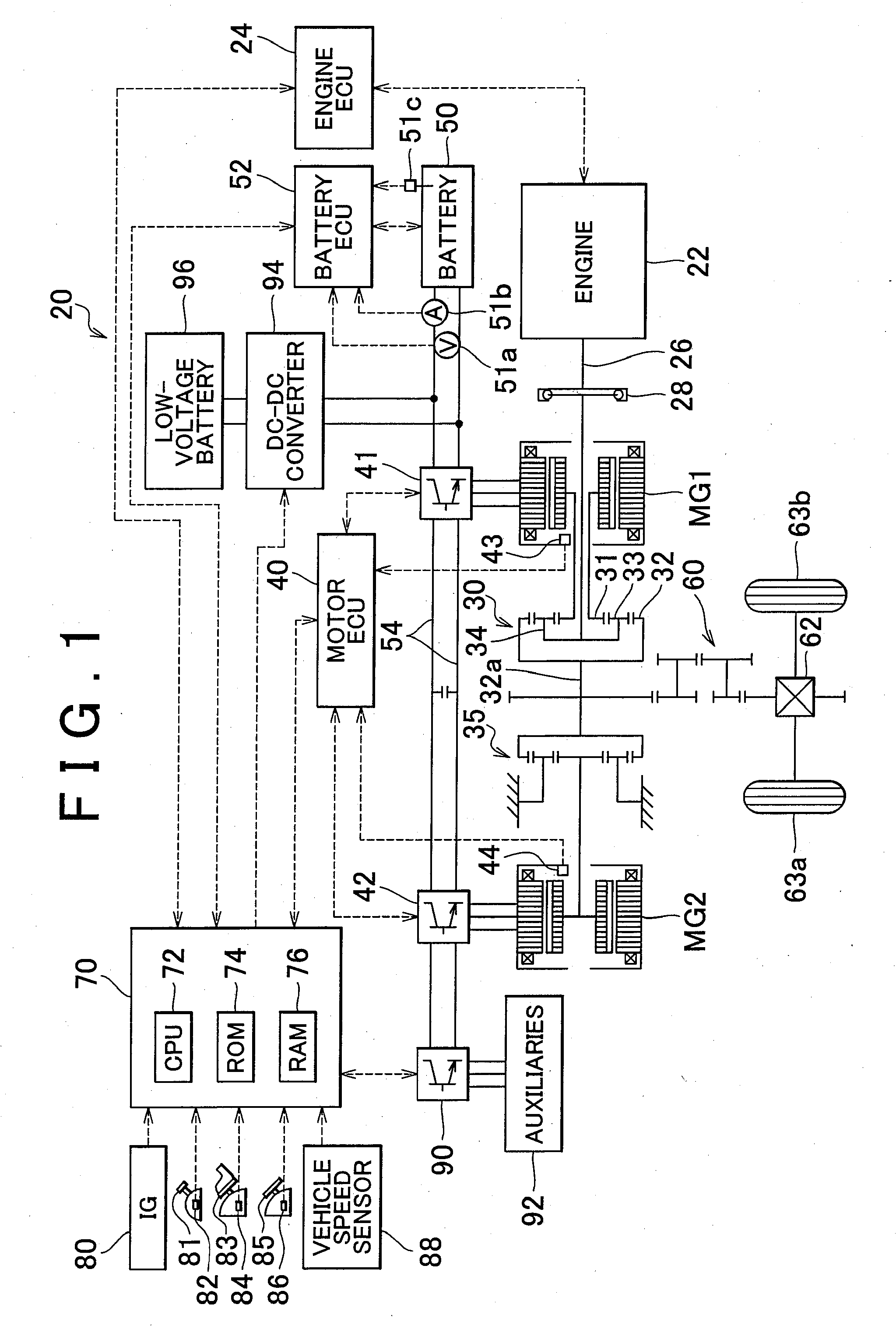
[0030]FIG. 1 is a view schematically showing the configuration of a hybrid vehicle 20 incorporating a drive force output apparatus according to an example embodiment of the invention. Referring to FIG. 1, the hybrid vehicle 20 has an engine 22, a three-shaft type drive force distribution-combination mechanism 30 connected to a crankshaft 26, which is the output shaft of the engine 22, via a damper 28, an electric motor MG1 connected to the drive force distribution-combination mechanism 30 and capable of generating power, a reduction gear unit 30 coupled with a ring gear shaft 32a that is a drive shaft in this example embodiment and connected to the drive force distribution-combination mechanism 30, a motor MG2 connected to the reduction gear unit 35, and a hybrid electronic control unit (will be referred to as “hybrid ECU”) 70 that governs the overall control of the entire drive force output apparatus.

[0031]The engine 22 is an internal combustion engine that runs on hydrocarbon fuel...


PUM


Abstract

A drive force output apparatus has a controller that sets an upper limit of power allowed to be consumed by an auxiliary based on at least a reference power storage amount corresponding to the reference of the range in which the power storage amount of a power storage is monitored and controls a power generator, an electric motor, and the auxiliary such that drive force corresponding to target drive force is output to a drive shaft while the power consumed by the auxiliary remains equal to or smaller than the upper limit.

Description

INCORPORATION BY REFERENCE[0001]The disclosure of Japanese Patent Application No. 2007-301290 filed on Nov. 21, 2007 including the specification, drawings and abstract is incorporated herein by reference in its entirety.BACKGROUND OF THE INVENTION[0002]1. Field of the Invention[0003]The invention relates to a drive force output apparatus, a method for controlling a drive force output apparatus, and a vehicle.[0004]2. Description of the Related Art[0005]Japanese Patent Application Publication No. 2003-47108 (JP-A-2003-47108) describes a drive force output apparatus having a drive motor, a power generator that generates power using the drive force of an engine, an inverter that drives the drive motor and the power generator, and a nickel metal hydrogen battery that exchanges power with the inverter, and the drive force output apparatus. This drive force output apparatus controls the engine, the power generator, and the drive motor so as to output a target torque set based on the opera...

Claims


Application Information

Patent Timeline
Patent Type & Authority Applications(United States)
IPC IPC(8): B60W10/08G06F17/00B60W20/00
CPCB60K1/02Y10T477/30B60K6/365B60K6/445B60K6/448B60K6/547B60L2240/421B60L2240/423B60L2240/486B60W10/06B60W10/08B60W10/30B60W20/00B60W2510/244B60W2510/246B60W2520/10B60W2540/10B60W2540/12B60W2540/16B60W2710/0644B60W2710/0666B60W2710/081B60W2710/083Y02T10/6243Y02T10/6286Y02T10/642Y02T90/34Y02T10/6239Y10T477/23B60K6/32Y02T10/62Y02T10/64Y02T90/40B60W20/13
Inventor SHAMOTO, SUMIKAZU
Owner TOYOTA JIDOSHA KK
Why Eureka
Try Eureka