Method for the estimation of combustion parameters

a technology of combustion parameters and estimation methods, applied in the direction of electrical control, instruments, nuclear elements, etc., can solve the problems that the measurement of such sensors cannot be used, and the determination of proper control actions may be difficult without reliable estimates, so as to improve the quality and robustness of estimates. , the effect of high quality

Active Publication Date: 2009-05-21
ALTRONIC
View PDF5 Cites 38 Cited by
  • Summary
  • Abstract
  • Description
  • Claims
  • Application Information

AI Technical Summary

Benefits of technology

[0021]The invention is a method for estimating combustion parameters in internal combustion engines. It widens known strategies for combustion parameter estimation by using prior knowledge. This is done by a linear or non-linear transform of measurement data to a representation that is used in an algorithm for detection or estimation of combustion parameters. The invention can be divided into...

Problems solved by technology

The measurements from such sensors cannot be used as they are in a closed engine control loop since they are not accurate and robust enough.
In many engine con...

Method used


Image

  • Method for the estimation of combustion parameters
  • Method for the estimation of combustion parameters
  • Method for the estimation of combustion parameters

Examples


example

[0079]It is well known how the AFR and PPL are related to each other. Assume a prior P2(k; X, Y) has been constructed for these two parameters. Consider the case when the measurement Y(k) takes a value that is different from, but much less likely than, the estimate X(k−1) achieved during the previous cycle. Then the new estimate X(k) should not be changed from (the more likely) X(k−1) to the.(less likely) measurement Y(k) since it may be disturbed by noise. The estimate should be updated “towards” the measurement Y(k), but not be set equal to Y(k). Preferably the updated estimate X(k) should be set to a value somewhere in-between X(k−1) and Y(k), depending on the value of the estimated risk R2(k; X, Y) to move from state X(k−1) to Y(k).

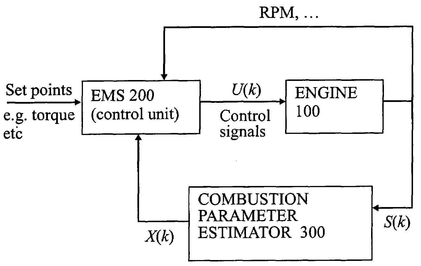
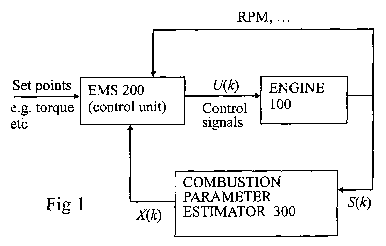
[0080]Figured shows a second method to obtain a combustion parameter estimate X(k) of higher quality than the measurement Y(k) using a prior P2(k; X, Y) and the former estimate X(k−1).

[0081]In step 201 of FIG. 4 estimated values of the parameters from...


PUM


Abstract

Method for combustion engine control comprising an engine, at least one sensor and at least one engine control unit (200) arranged to control the engine (100) by the use of real time sensor data S(k) characterized in that a prior (P1(k, j; z), P2(k ; X, Y) is used to derive at least one combustion parameter estimate (X(k)) and/or al least one combustion parameter measurement (Y(k)) from the real lime sensor data (S(k)) and that the at least one combustion parameter estimate (X(k)) and/or the at least one combustion parameter measurement (Y(k)) is used in performing said engine control.

Description

TECHNICAL FIELD[0001]The present invention relates to method for controlling a combustion engine, more specific the method concerns estimating combustion parameter from sensor data input. Such combustion parameter estimates can be used by an engine control system for optimizing the performance of the engine and enable close loop real-time strategies for the engine control.BACKGROUND OF THE INVENTION[0002]Due to the hostile environment in the cylinders, it is a challenge to retrieve necessary information about the combustion process cycle-by-cycle. Without such information, it is impossible to optimize the overall engine efficiency and stability and to minimize emissions.[0003]Control of Otto engines basically amounts to controlling three primary variables: ignition timing and fuel and air injected into the cylinder. For the two latter both the mass and the timing are important and these are controlled separately using different actuators such as the throttle, the fuel injectors, and...

Claims


Application Information

Patent Timeline
IPC IPC(8): F02D43/00
CPCF02D35/02F02D35/023F02D41/1458F02D41/2422G01L23/227F02D2200/1004F02D35/021F02D2041/286F02D41/2477
Inventor ANGEBY, JACOB
Owner ALTRONIC
Why Eureka
Try Eureka