Device and Means of Processing a Material by Means of an Ultrasonic Device

a technology of ultrasonic processing and material, applied in the direction of domestic articles, lamination, etc., can solve the problems of difficult control of the method of ultrasonic processing, material and stationary ultrasound horn friction, etc., to improve the processing process, optimize the ultrasound process, and increase the process window

Inactive Publication Date: 2009-05-28
SCA HYGIENE PROD AB
View PDF3 Cites 16 Cited by
  • Summary
  • Abstract
  • Description
  • Claims
  • Application Information

AI Technical Summary

Benefits of technology

[0015]Certain significant advantages are achieved, Firstly, it can be noted that the above-mentioned undesired effects in the form of friction and mechanical compression of the material at the ultrasound horn can be minimized, which gives an increased process window and a more stable process for processing with the ultrasonic device. This is particul

Problems solved by technology

A side effect of the procedure described above for the ultrasonic processing of material is that friction occurs between the material and the stationary ultrasound horn when the material is fed past the ultrasound horn.
Energy losses occur in this way as a consequence of this compression while the material is being caused to advance continuously in its longitudinal direction in relation to the stationary ultrasound horn.
Friction thus occurs in this way through the contact between the material and the surface of the ultrasound horn, together with energy losses as a consequence of the mechanical compression of the material.
All in all, this leads to a method of ultrasoni

Method used


Image

  • Device and Means of Processing a Material by Means of an Ultrasonic Device
  • Device and Means of Processing a Material by Means of an Ultrasonic Device
  • Device and Means of Processing a Material by Means of an Ultrasonic Device

Examples


Embodiment Construction

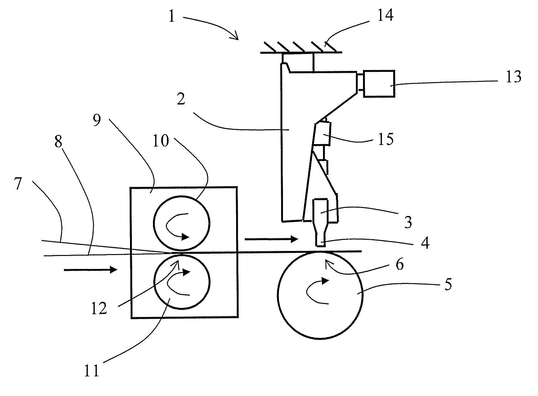
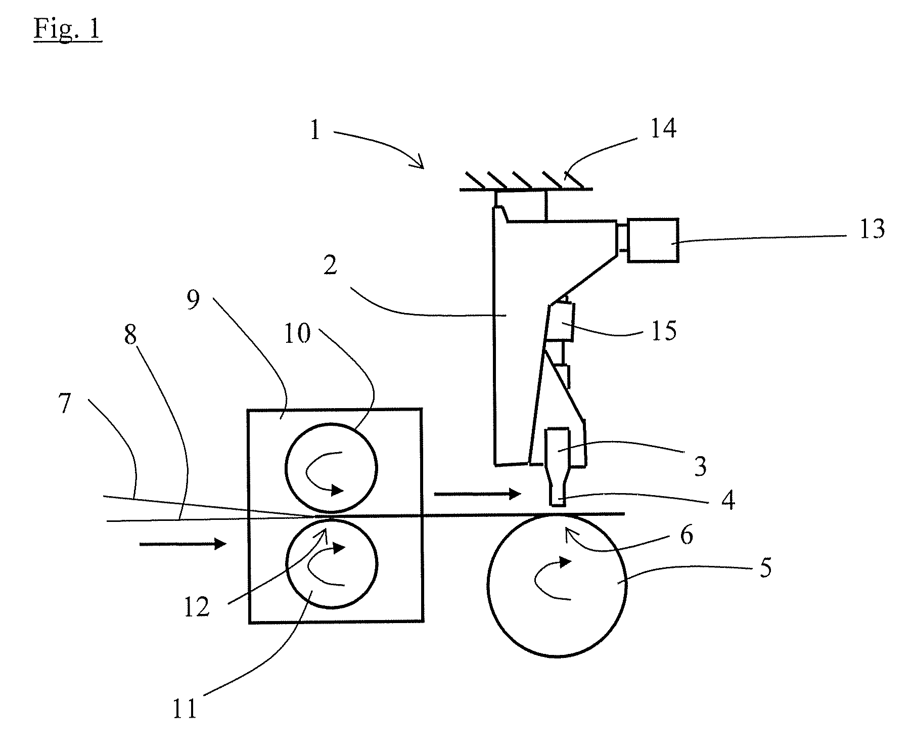
[0022]FIG. 1 is a schematic side view of an arrangement 1 for ultrasound processing, which is intended for use in conjunction with the present invention. More specifically, in accordance with the prior art, the arrangement 1 comprises an ultrasonic device 2 with an ultrasound horn 3, which in turn is executed with a contact device 4, that is to say an end part.

[0023]It can also be appreciated from FIG. 1 that the ultrasonic device 2 is arranged in close proximity to a rotating abutment roller 5, the periphery of which defines an abutment surface. The abutment roller 5 is also appropriately provided with patterns intended to contribute to the ultrasound processing in question. The contact device 4 of the ultrasound horn 3 also faces towards the material and is arranged with a small distance to the periphery of the abutment roller 5. A small gap 6 is formed in this way, that is to say a relatively small distance between the contact device 4 and the peripheral surface of the abutment r...


PUM

PropertyMeasurementUnit
Sizeaaaaaaaaaa
Mechanical propertiesaaaaaaaaaa

Abstract

An arrangement for processing of a material including at least one layer of material by an ultrasonic device having an ultrasound horn arranged adjacent to an abutment, in conjunction with which a gap is defined between the aforementioned ultrasound horn and the aforementioned abutment, in conjunction with which the aforementioned ultrasonic device is arranged for the purpose of feeding the aforementioned material through the aforementioned gap. The arrangement includes a pre-compression unit for the mechanical compression of the aforementioned material before it is fed through the aforementioned gap.

Description

TECHNICAL FIELD[0001]The present disclosure relates to an arrangement for processing of a material comprising at least one layer of material by an ultrasonic device an ultrasound horn arranged adjacent to an abutment, in conjunction with which a gap is defined between the aforementioned ultrasound horn and the aforementioned abutment, in conjunction with which the aforementioned ultrasonic device is arranged for the purpose of feeding the aforementioned material through the aforementioned gap.[0002]The disclosure also relates to a method for processing of a material comprising at least one layer of material by means of an ultrasonic device comprising an ultrasound horn arranged adjacent to an abutment, in conjunction with which the aforementioned method involves feeding the aforementioned material through a gap that is defined between the aforementioned ultrasound horn and the aforementioned abutment.BACKGROUND ART[0003]Ultrasound technology is used in certain processes that are arr...

Claims


Application Information

Patent Timeline
IPC IPC(8): B32B37/00
CPCA61F13/15707B29C66/727A61F2013/53991B29C65/02B29C65/086B29C65/56B29C66/022B29C66/0222B29C66/21B29C66/8242B29C66/83411B29C66/83413B29C66/83415B29C66/92611B29K2023/00B29K2023/06B29K2023/12B29K2067/00B29K2077/00B29K2101/12B29K2105/04B29K2105/0854B29K2223/00B29L2009/00B29L2031/4878B32B37/00B32B38/0012B32B2305/20B32B2310/028A61F13/15739B29C66/81433B29C66/7294B29C65/00B29C66/9221B29C66/73921B29C66/71B29C66/1122B29C66/92445B29C66/73521B29K2023/04B29K2023/10
Inventor LEHTO, MARCUS
Owner SCA HYGIENE PROD AB
Why Eureka
Try Eureka