Heat dissipation device and assembly method thereof

a heat dissipation device and heat dissipation technology, applied in the direction of manufacturing tools, soldering devices, lighting and heating apparatus, etc., can solve the problems of heat pipe low heat transfer resistance, electrical components may overheat, and performance may be significantly degraded

Inactive Publication Date: 2009-05-28
FURUI PRECISE COMPONENT (KUNSHAN) CO LTD +1
View PDF5 Cites 11 Cited by
  • Summary
  • Abstract
  • Description
  • Claims
  • Application Information

AI Technical Summary

Problems solved by technology

If the generated heat is not rapidly and efficiently removed, the electronic component may overheat and the performance thereof may be significantly degraded.
The heat pipe has low thermal resistance in heat transfer due to a phase change mechanism employing working fluid in the heat pipe.
However, an air gap occurs between the heat pipe and the fins, reducing heat transmission efficiency from the heat pipe to the fins.
However, due to its viscosity at normal temperatures, it is difficult for the solder paste to spread evenly throughout the length of the tunnel, with particles of the metal alloy of the solder paste becoming more unevenly distributed after the heat pipe is received.
The quality of the join between the heat pipe and the metal fins is affected, which reduces heat exchange efficiency.
Further, the solder paste is easily forced out of the tunnel of the fin assembly when the heat pipe is inserted, wasting the solder paste.

Method used


Image

  • Heat dissipation device and assembly method thereof
  • Heat dissipation device and assembly method thereof
  • Heat dissipation device and assembly method thereof

Examples


Embodiment Construction

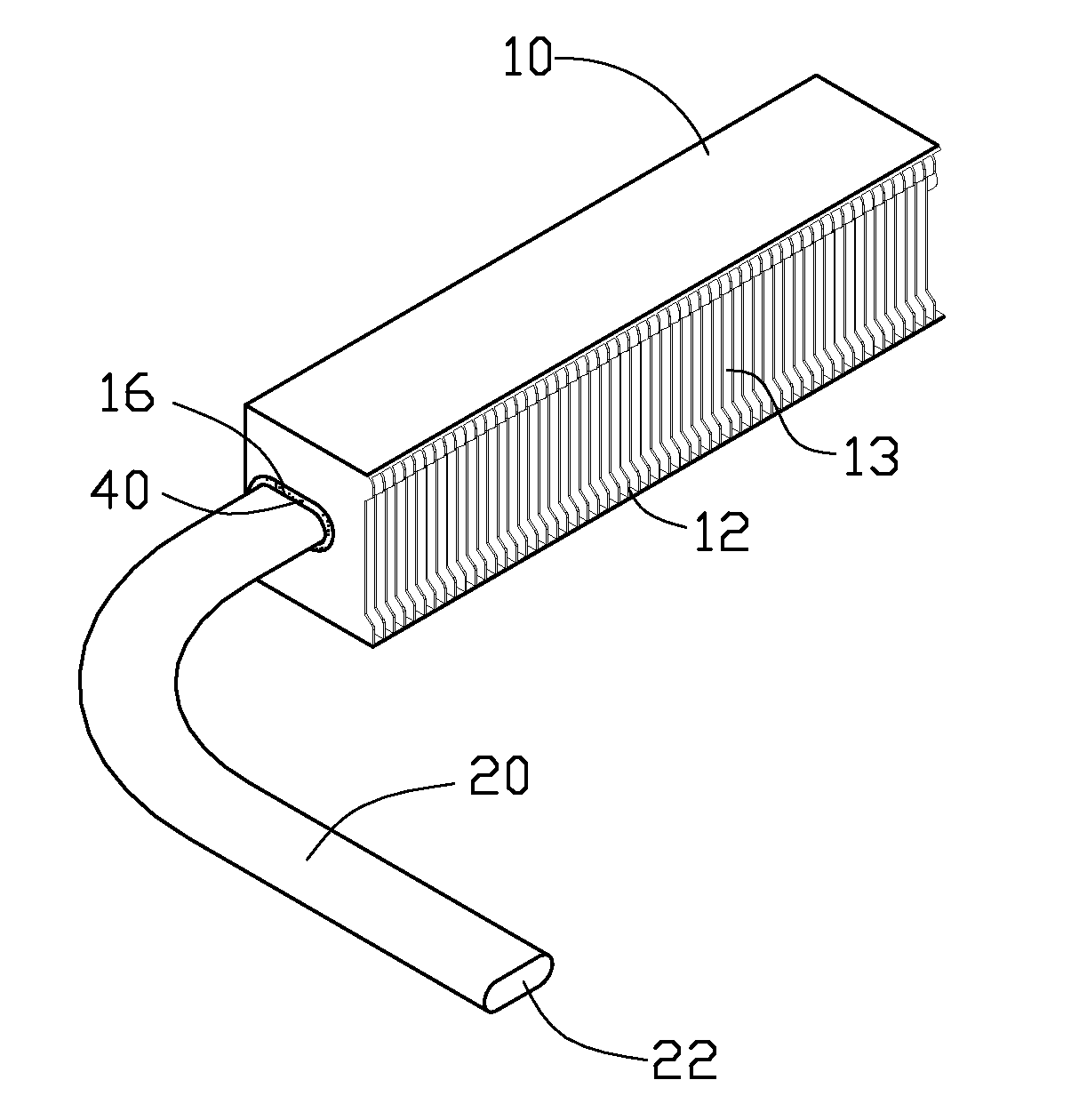
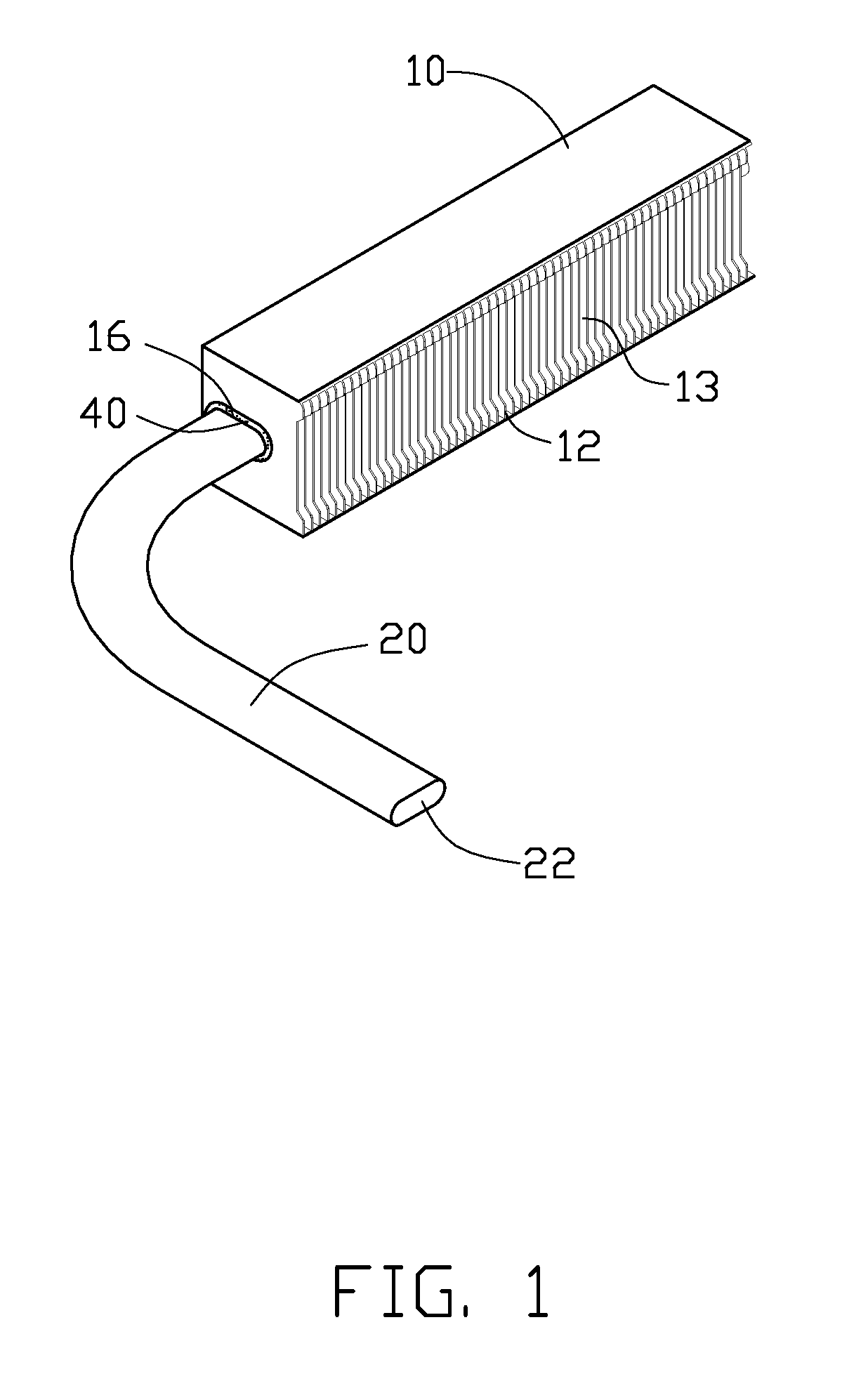
[0012]Referring to FIGS. 1 and 2, a heat dissipation device in accordance with a first embodiment is shown. The heat dissipation device includes a heat sink 10, a flat heat pipe 20 extending into the heat sink 10, and a solder layer 40 filled between the heat sink 10 and the heat pipe 20.

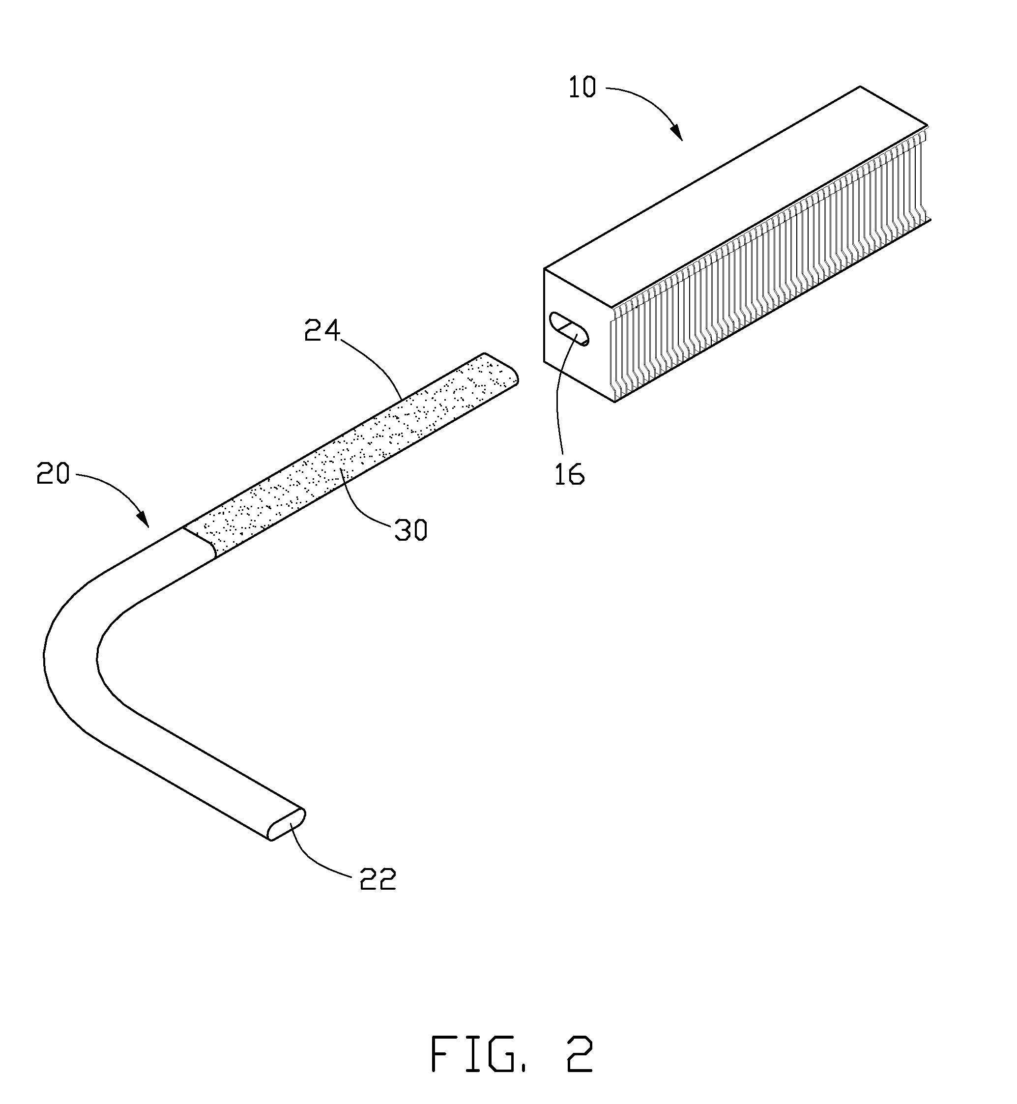
[0013]The heat sink 10 includes a plurality of stacked parallel fins 12. A plurality of air passages 13 are formed between the fins 12 through which cooling air flows. Each of the fins 12 is substantially rectangular and defines a substantially elliptical aperture 16 in a center portion thereof, receiving the heat pipe 20.

[0014]The heat pipe 20 is L-shaped and includes an evaporator section 22 thermally contacting an electronic component (not shown), and a condenser section 24 with a layer of solid-state solder film 30 coated thereon. The solid-state solder film 30 is coated on an exterior surface of the condenser section 24 before the heat pipe 20 is inserted into the heat sink 10. The solid-state ...


PUM

PropertyMeasurementUnit
thickaaaaaaaaaa
thickaaaaaaaaaa
temperaturesaaaaaaaaaa

Abstract

A heat dissipation device includes a heat pipe having a condenser section and a layer of solid-state solder film on an exterior surface of the condenser section, a heat sink having a plurality of spaced fins, each of which has an aperture. The condenser section of the heat pipe fits into the apertures of the fins. The heat sink with the condensing section received therein is heated and the solid-state solder film melts, filling gaps between the heat pipe and the fins. A method of assembling the device is also provided.

Description

BACKGROUND[0001]1. Field of the Disclosure[0002]The disclosure generally relates to heat dissipation, and particularly to a heat dissipation device incorporating a heat pipe and fins and an assembly method thereof.[0003]2. Description of Related Art[0004]It is well-known that heat is generated by electronic components such as central processing units (CPUs). If the generated heat is not rapidly and efficiently removed, the electronic component may overheat and the performance thereof may be significantly degraded. Generally, a heat dissipation device including a heat pipe and a plurality of fins is used for cooling a CPU. The heat pipe has low thermal resistance in heat transfer due to a phase change mechanism employing working fluid in the heat pipe. The heat pipe includes an evaporator section thermally contacting the CPU and a condenser section. The fins are connected to the condenser section, dissipating heat transferred from the CPU by the heat pipe. However, an air gap occurs ...

Claims


Application Information

Patent Timeline
Patent Type & Authority Applications(United States)
IPC IPC(8): F28D15/00B23P11/00
CPCB23K1/0012B23K2201/14F28D15/0233F28D15/0266Y10T29/49826F28F21/089F28F2215/12F28D15/0275F28F1/24B23K2101/14
Inventor HSIEH, YI-SHIHRAO, JIN-JUN
Owner FURUI PRECISE COMPONENT (KUNSHAN) CO LTD
Why Eureka
Try Eureka