Electrostatic atomizer and coolant-circulating equipment including same

a technology of atomizer and coolant, which is applied in the direction of air humidification system, lighting and heating apparatus, heating types, etc., can solve the problems of cumbersome water-refill operation, obstructing water supply, and difficulty in reducing the total size of the instrument, so as to facilitate the formation of condensate water. , the effect of facilitating the formation of condensate water

Inactive Publication Date: 2009-05-28
MATSUSHITA ELECTRIC WORKS LTD
View PDF2 Cites 13 Cited by
  • Summary
  • Abstract
  • Description
  • Claims
  • Application Information

AI Technical Summary

Benefits of technology

[0010]In this way, by separating the condensation space from the cooling space by the partition wall, the condensation space can be maintained under higher temperature and absolute humidity conditions compared to the cooling space, that is, in a state of facilitating the formation of the condensate water on the atomizing electrode.
[0011]In addition, the coolant-circulating equipment may further include an air flow passage for guiding air heated by the heat-radiating part of the cooling cycle into the condensation space. In this way, an area of the condensation space can be maintained under higher temperature and absolute humidity conditions, that is, in a state which facilitates the formation of the condensate water on the atomizing electrode.
[0012]Alternatively, the heat-radiating part of the cooling cycle or a heat transfer member connected to the h...

Problems solved by technology

This type of water supplier requires a user to refill the water tank with water on a regular basis, undesirably causing a problem in which a user is obliged to spend time and effort for the cumbersome water-refilling operation.
Also, in the conventional electrostatic atomizer, in the case where water containing impurities such as Ca or Mg, for example tap water, is used as the supply water, such impurities entail a problem in that they react wit...

Method used


Image

  • Electrostatic atomizer and coolant-circulating equipment including same
  • Electrostatic atomizer and coolant-circulating equipment including same
  • Electrostatic atomizer and coolant-circulating equipment including same

Examples


Embodiment Construction

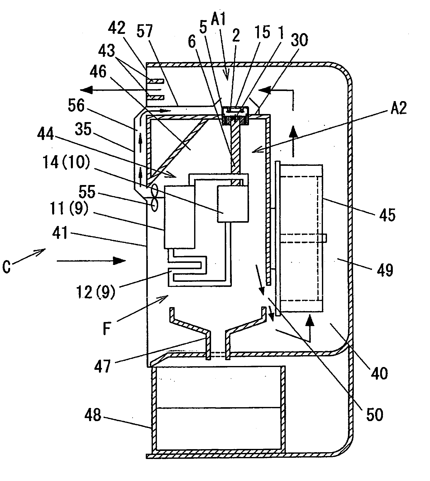
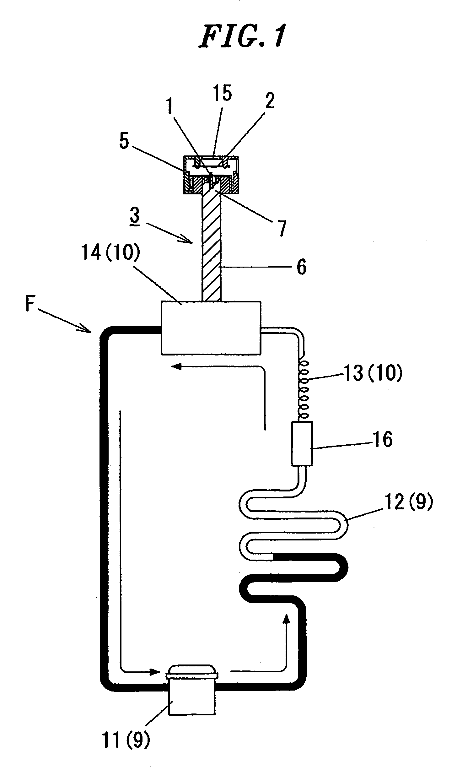
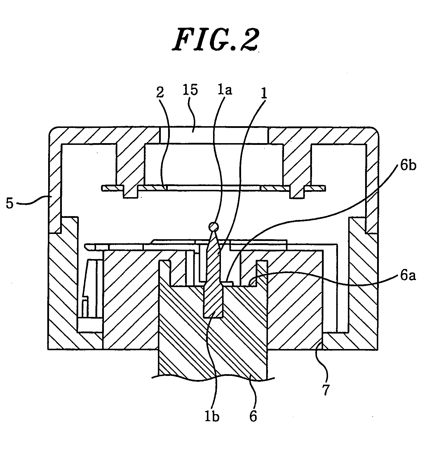
[0023]Hereinafter, a detailed description will be given of embodiments of the present invention with reference to the accompanying drawings. FIGS. 1 and 2 schematically show an electrostatic atomizer in accordance with an embodiment of the present invention.

[0024]The electrostatic atomizer in accordance with the present embodiment includes an atomizing electrode 1, a counter electrode 2 located to face the atomizing electrode 1, a cooling unit 3 for producing condensate water on the atomizing electrode 1 by condensing moisture in the air, a high voltage applying unit (not shown) for applying high voltage between the atomizing electrode 1 and the counter electrode 2, a control unit (not shown) for controlling the operation of electrostatic atomization, and an atomizer housing 5 receiving therein the above components. When high voltage is applied between the atomizing electrode 1 and the counter electrode 2 using the high voltage applying unit, water held on the atomizing electrode 1 ...


PUM


Abstract

An electrostatic atomizer includes an atomizing electrode to which a high voltage is applied to atomize water held on the atomizing electrode so as to generate charged water particles; and a cooling unit for producing water, to be supplied to the atomizing electrode, through condensation. The cooling unit is made using a cooling part of a cooling cycle which circulates a coolant between a heat-radiating part and the cooling part. A coolant-circulating equipment incorporating the electrostatic atomizer therein includes a condensation space in which the atomizing electrode is disposed to produce condensate water; a cooling space in which the cooling section of the cooling cycle is disposed to produce cold air; and a partition wall for separating the condensation space from the cooling space.

Description

FIELD OF THE INVENTION [0001]The present invention relates to an electrostatic atomizer for producing electrically charged water particles using an electrostatic atomization phenomenon.BACKGROUND OF THE INVENTION [0002]Conventionally, there has been known an electrostatic atomizer in which high voltage is applied to an atomizing electrode to atomize water held on the atomizing electrode so as to generate electrically charged water particles having a nanometer size and carrying a large number of electric charges. The charged water particles having a nanometer size has not only a moisturizing effect, but also a deodorizing effect, a disinfecting effect on molds and bacteria, and a suppressive effect on the propagation thereof, since active species exist therein in a state of being wrapped with water molecules. Further, the charged water particles having a nanometer size exhibit a longer life span as compared with active species existing independently in the form of free radicals, and ...

Claims


Application Information

Patent Timeline
IPC IPC(8): B05B5/16B05B17/04
CPCB05B5/057Y02B30/80F24F2006/125F24F3/14Y02B30/70
Inventor YAMAGUCHI, TOMOHIRO
Owner MATSUSHITA ELECTRIC WORKS LTD
Why Eureka
Try Eureka