
Method for controlling a direct current chopper controller

a chopper controller and direct current technology, applied in the direction of electric variable regulation, efficient power electronics conversion, instruments, etc., can solve the problems of discontinuous (gapping type) operation in the partial load region, and achieve the effect of improving the partial load region efficiencies

Active Publication Date: 2009-05-28
KOSTAL IND ELEKTRIK
View PDF9 Cites 15 Cited by
  • Summary
  • Abstract
  • Description
  • Claims
  • Application Information

AI Technical Summary

Benefits of technology

[0006]An object of the present invention is a method for operating a direct current (“DC”) chopper controller such that improved efficiencies in the partial-load region are obtained.
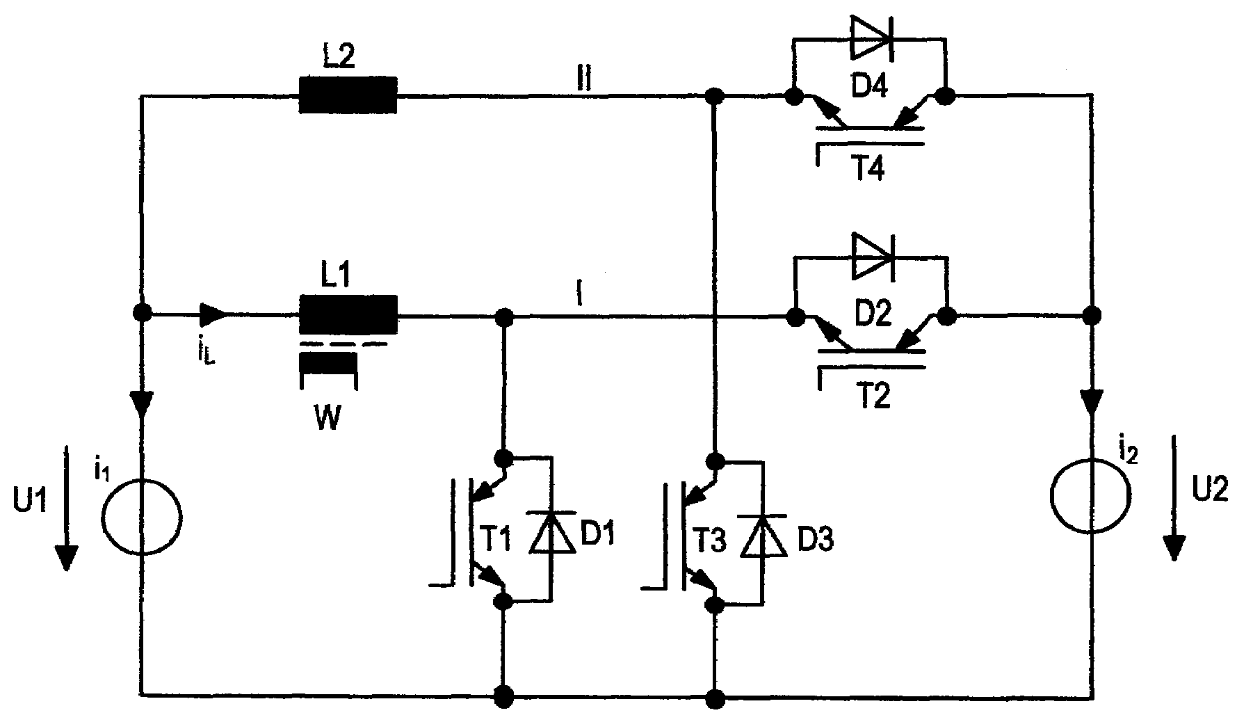
[0010]In the case of a DC chopper controller having a plurality of parallel current channels, which are driven sequentially as a function of the current detected in a first one of the current channels (the master channel), a load-dependent activation and deactivation of the remaining current channels (the slave channels) is provided. The current in the master channel and possibly in some of the slave channels is increased by the deactivation of the slave channels. This results in increased magnetic reversal and line losses. However, the switching losses of the switches of the controller are reduced so that an overall increase in efficiency can be achieved.
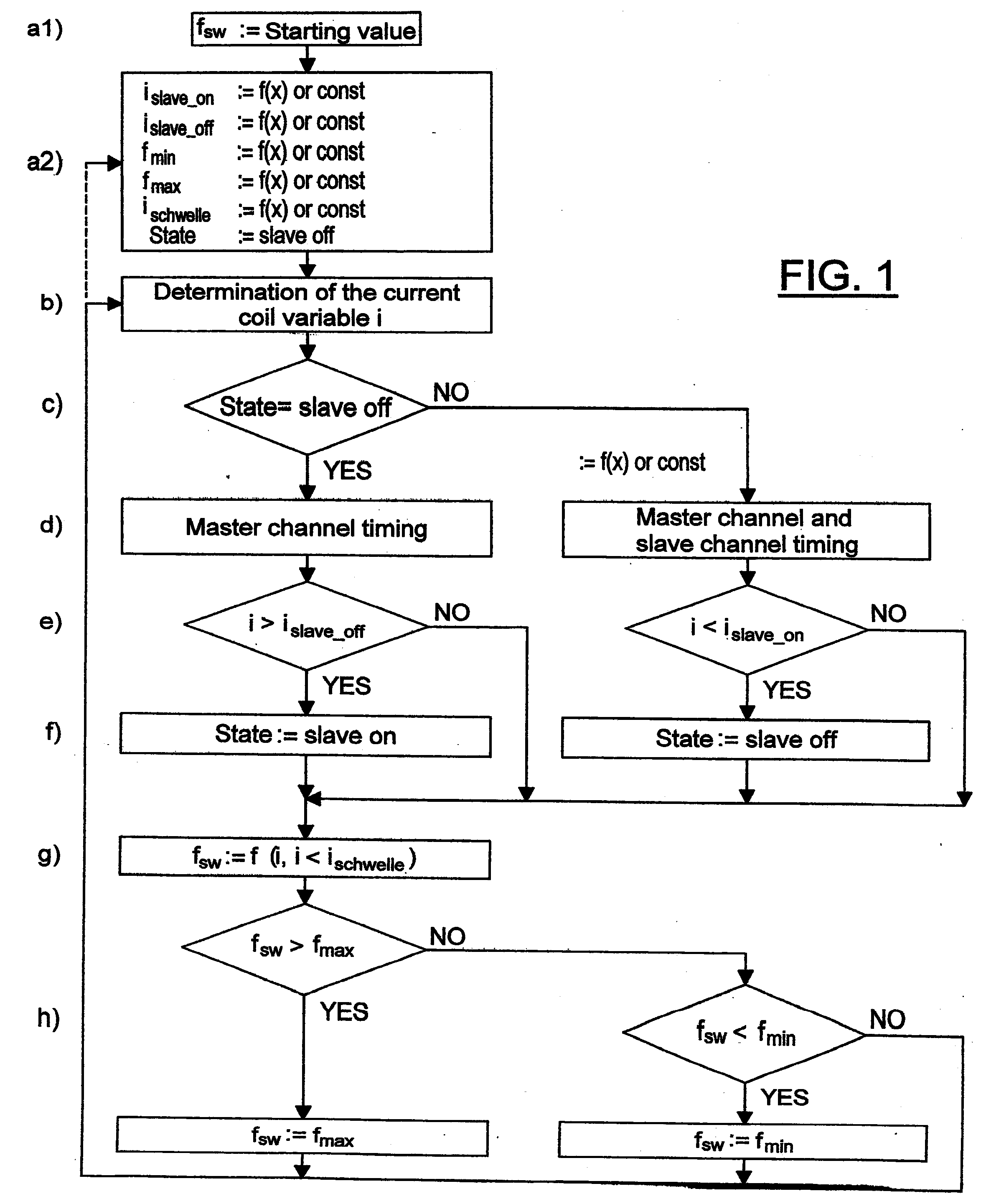
[0011]As such, embodiments of the present invention provide a method of controlling a DC chopper controller having at least one semiconductor switch that is controllable by a micro-controller and a storage choke. The switching frequency for synchronizing the switch(es) is calculated in the partial-load region and is limited to a value between a minimum value and a maximum value. In the case of the controller having multiple current channels (a master channel and slave channels), a load-dependent activation and deactivation of the slave channels can be provided. An improvement in the efficiency is thereby achieved in the partial-load region.

Problems solved by technology

This leads to a discontinuous (i.e., gapping type) operation in the partial-load region.

Method used


Image

  • Method for controlling a direct current chopper controller
  • Method for controlling a direct current chopper controller
  • Method for controlling a direct current chopper controller

Examples


Embodiment Construction

)

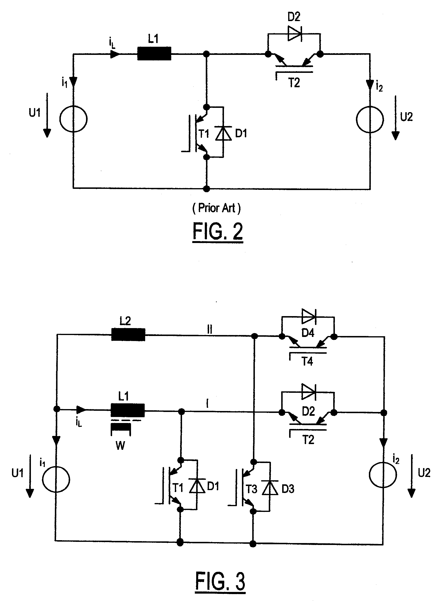
[0017]Referring now to FIG. 2, a circuit diagram of a bidirectional direct current (“DC”) chopper controller is shown. The controller includes first and second voltage sources U1, U2, a storage choke (inductor) L1, and first and second semiconductor switches T1, T2. Each switch T1, T2 is an insulated gate bipolar transistor. A first free-running diode D1 is connected in parallel to first switch T1. A second free-running diode D2 is connected in parallel to second switch T2.

[0018]Switches T1, T2 are connected with the other components such that for an interconnected first switch T1 storage choke L1 is connected through first switch T1 to first voltage source U1 and such that for an interconnected second switch T2 storage choke L1 is connected in series to second switch T2 and first and second voltage sources U1, U2.

[0019]A functional principle of the controller is that by switching on one of switches (T1 and / or T2), storage choke L1 is subjected to current flow that builds up a magn...


PUM


Abstract

A method of controlling a direct current (“DC”) chopper controller having a switch and a storage choke in which the choke has a current dependent on the switching of the switch on and off includes the following. A current variable derived from one of the time averaged value of the current of the choke and the peak value of the current of the choke is determined. A switching frequency for synchronizing the turning on and off the switch is calculated as a function of the current variable and on whether the current variable exceeds a current threshold. The switching frequency is determined to be a predetermined low frequency if the switching frequency is lower than the low frequency and is determined to be a predetermined high frequency if the switching frequency is greater than the high frequency. The switch is switched on and off in accordance with the switching frequency.

Description

CROSS-REFERENCE TO RELATED APPLICATIONS[0001]This application claims foreign priority benefits under 35 U.S.C. §119(a)-(d) to DE 10 2007 057 230.3, filed Nov. 28, 2007, which is hereby incorporated by reference in its entirety.BACKGROUND OF THE INVENTION[0002]1. Field of the Invention[0003]The present invention relates to a method for controlling a direct current chopper controller which has at least one current channel with each current channel having a storage choke and semiconductor switches which are controllable by a micro-controller.[0004]2. Background Art[0005]DE 10 2007 041 510 describes a direct current (“DC”) chopper controller which may operate either as a step-up converter or a step-down converter. The controller includes multiple current channels each including a storage choke and semiconductor switches. A micro-controller is operable to control the switches. The controller is operated at the edge of the gap (i.e., in the transition-mode) as switching losses of the swit...

Claims


Application Information

Patent Timeline
IPC IPC(8): G05F1/00
CPCH02M3/1584Y02B70/1466H02M3/1588Y02B70/10H02M1/0032
Inventor LANDWEHR, FRANK
Owner KOSTAL IND ELEKTRIK
Learn More