Corrosion evaluation device and corrosion evaluation method
a corrosion evaluation and corrosion technology, applied in the direction of instruments, electrical/magnetic thickness measurements, material magnetic variables, etc., can solve the problems of difficult inability to perform quantitative evaluation of corrosion, etc., to achieve the effect of higher magnetic sensitivity
- Summary
- Abstract
- Description
- Claims
- Application Information
AI Technical Summary
Benefits of technology
Problems solved by technology
Method used
Image
Examples
application example 1
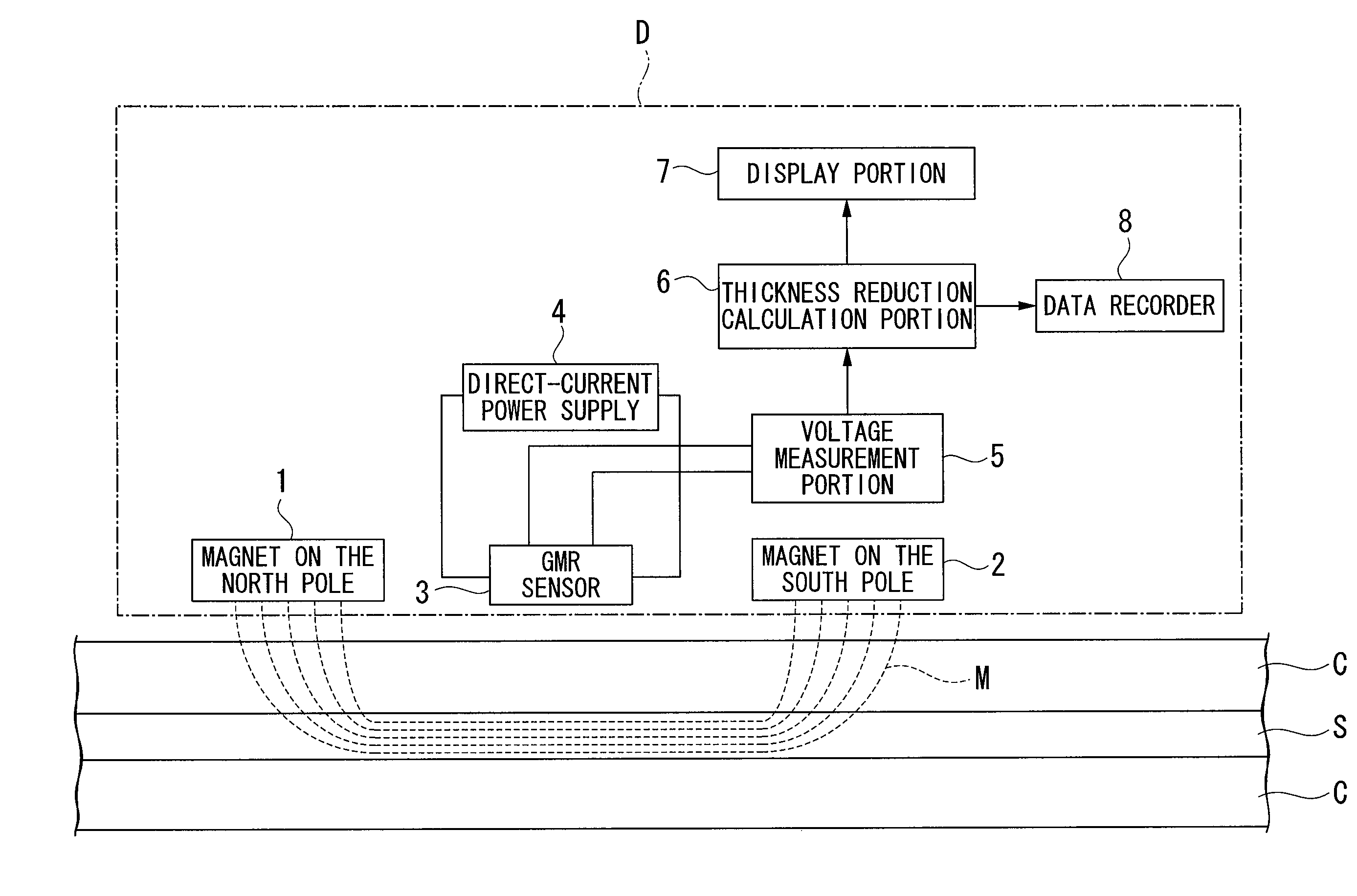
[0067]FIG. 8 shows an application example of the corrosion evaluation device D. As shown in FIG. 8, the corrosion evaluation device D is disposed in the bogie 10 which is able to move itself by program control. The bogie 10 moves two-dimensionally along the concrete C which covers the reinforcing steel S and measures the quantity of decrease in the thickness at each of the predetermined measurement points. The quantity of decrease in the thickness measured at each of the measurement points is stored in the data recorder 8 one by one. In order to maintain the detection accuracy of the magnetic flux leakage, it is preferable to maintain a distance between the surface of the reinforcing steel S and the GMR sensor 3 (measurement gap) constant. However, the surface of the concrete C is not always horizontal in accordance with measurement points on the surface of the concrete C. Accordingly, the bogie 10 has a function to compensate the measurement gap at each of the measurement points in...
application example 2
[0069]FIG. 9 shows an application example 2 of the corrosion evaluation device D. As shown in FIG. 9, the corrosion evaluation device D of the application example 2 has a probe 20 provided with the magnet 1 on the north pole, the magnet 2 on the south pole, and the GMR sensor 3, and an operation box 22 connected via the probe 20 and a cable 21 provided with the direct-current power supply 4, a voltage measurement portion 5, the thickness reduction calculation portion 6, the display portion 7, and the data recorder 8. An operator 30 moves the probe 20 which is held in one hand to a preferred measurement point along the surface of the concrete C which covers the reinforcing steel S. At this time, the operator visually confirms the quantity of decrease in the thickness which is displayed on the display portion 7 of the operation box 22 and can recognize the progress of corrosion if any.
[0070]In accordance with the application example 2 as described above, it is possible to effectively ...
PUM
 Abstract
Description
Claims
Application Information
 - R&D
- Intellectual Property
- Life Sciences
- Materials
- Tech Scout
- Unparalleled Data Quality
- Higher Quality Content
- 60% Fewer Hallucinations
Browse by: Latest US Patents, China's latest patents, Technical Efficacy Thesaurus, Application Domain, Technology Topic, Popular Technical Reports.
© 2025 PatSnap. All rights reserved.Legal|Privacy policy|Modern Slavery Act Transparency Statement|Sitemap|About US| Contact US: help@patsnap.com


