Image taking apparatus and image recorder

a technology of image recording and image processing, applied in the field of image sensors, can solve the problems of increasing probability, short exposure time, and no description about a specific exposure timing (interlaced step), and achieve the effect of accurately taking an imag

Inactive Publication Date: 2009-05-28
SEIKO EPSON CORP
View PDF10 Cites 107 Cited by
  • Summary
  • Abstract
  • Description
  • Claims
  • Application Information

AI Technical Summary

Benefits of technology

[0013]An advantage of the invention is to provide an image taking apparatus and an image recorder suitable for accurately taking an image of a subject that lights up and lights out cyclically when emitting light.
[0014]According to a first aspect of the invention, an image taking apparatus includes: a photoelectric conversion unit including a plurality of photoelectric conversion elements, the photoelectric conversion elements disposed in a two-dimensional matrix, the photoelectric conversion elements converting received light into electric charge and accumulating the electric charge; an image sensor having a function of controlling an exposure time of each of the photoelectric conversion elements of the photoelectric conversion unit on a line-by-line basis; an area division unit for logically dividing the photoelectric conversion unit into an N number (N is a natural number of two or more) of uniform areas on the basis of information related to a taken image of a subject, each of the uniform areas including a line having some of the photoelectric conversion elements; an interlaced scanning unit for scanning the photoelectric conversion elements in the first to N-th areas by M lines (M is a natural number of one or more) starting with a predetermined line in a predetermined area of the first to N-th areas in each frame while changing an area to be scanned to another area in a predetermined order each time the M lines are scanned; a pixel signal reading unit for reading, from each of the photoelectric conversion elements scanned by the interlaced scanning unit, a pixel signal including an electric signal corresponding to an amount of electric charge accumulated in each photoelectric conversion element; and a scanning timing control unit for controlling a timing at which the interlaced scanning unit performs scanning, on the basis of a time of each frame and an

Problems solved by technology

However, there is no description about a specific exposure timing (interlaced step) for accurately taking an image of a flashing subject such as an LED traffic signal under a condition in which the exposure time is extremely short, such as outdoors i

Method used


Image

  • Image taking apparatus and image recorder
  • Image taking apparatus and image recorder
  • Image taking apparatus and image recorder

Examples


first embodiment

[0051]Now, an image taking apparatus and an image recorder according to a first embodiment of the invention will be described with reference to the accompanying drawings. FIGS. 1 to 10 are diagrams showing the image taking apparatus and image recorder according to this embodiment.

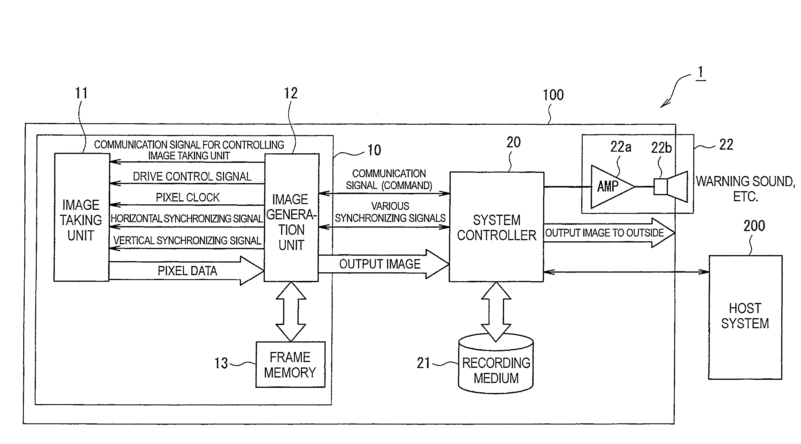
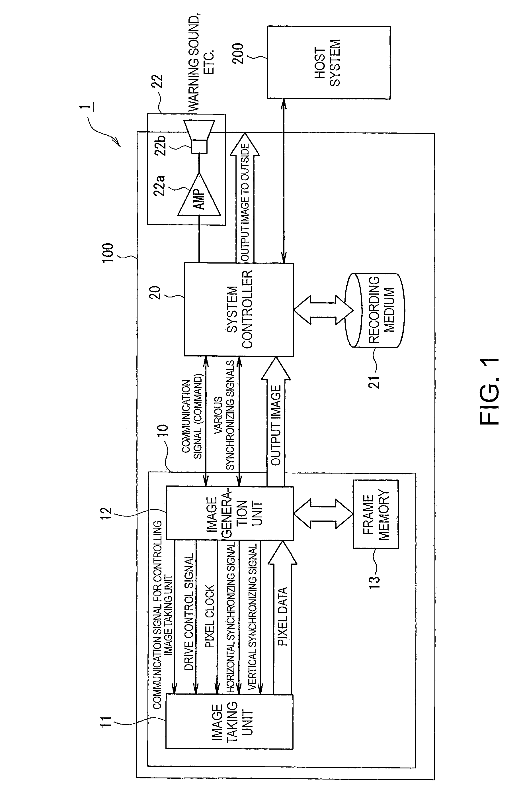
[0052]Referring now to FIG. 1, an outline configuration of an image taking system 1 according to this embodiment will be described. FIG. 1 is a block diagram showing an outline configuration of the image taking system 1 according to this embodiment. As shown in FIG. 1, the image taking system 1 includes an image recorder 100 and a host system 200. The image recorder 100 and host system 200 are coupled to each other so as to communicate data to each other.

[0053]The image recorder 100 includes an image taking apparatus 10 for taking an image of a subject, a system controller 20 for recording image data generated by the image taking apparatus 10 and determining information about interlaced scanning, a recordin...

second embodiment

[0156]Hereafter, an image taking apparatus and an image recorder according to a second embodiment of the invention will be described with reference to the accompanying drawings. FIG. 11 is a diagram showing the image taking apparatus and image recorder according to this embodiment.

[0157]The configuration of an image taking system according to this embodiment is similar to that of the image taking system 1 according to the above-mentioned first embodiment except that a method for dividing the light receiving area according to this embodiment is different from that according to the first embodiment.

[0158]The area division method according to this embodiment is suitable for a case where the exposure time is extremely small (e.g., a case where the division area number is small, e.g., 2 or 3, in the first embodiment), information about the flashing cycle of a flashing light source is known, and the time during which the light source lights up is equal to or longer than the time during wh...


PUM


Abstract

An image taking apparatus includes: a photoelectric conversion unit including a plurality of photoelectric conversion elements, the photoelectric conversion elements disposed in a two-dimensional matrix, the photoelectric conversion elements converting received light into electric charge and accumulating the electric charge; an image sensor having a function of controlling an exposure time of each of the photoelectric conversion elements of the photoelectric conversion unit on a line-by-line basis; an area division unit for logically dividing the photoelectric conversion unit into an N number of uniform areas on the basis of information related to a taken image of a subject, each of the uniform areas including a line having some of the photoelectric conversion elements, N being a natural number of two or more; an interlaced scanning unit for scanning the photoelectric conversion elements in the first to N-th areas by M lines starting with a predetermined line in a predetermined area of the first to N-th areas while changing an area to be scanned to another area in a predetermined order each time the M lines are scanned, M being a natural number of one or more; and a pixel signal reading unit for reading, from each of the photoelectric conversion elements scanned by the interlaced scanning unit, a pixel signal including an electric signal corresponding to an amount of electric charge accumulated in each photoelectric conversion element.

Description

BACKGROUND[0001]1. Technical Field[0002]Several aspects of the present invention relate to an image sensor that is allowed to expose a photoelectric conversion element to light on a line-by-line basis. In particular, the invention relates to an image taking apparatus and an image recorder suitable for accurately taking an image of a subject that lights up and lights out cyclically when emitting light.[0003]2. Related Art[0004]Recently, a drive recorder has been mounted on an automobile. This apparatus is intended to image and record the situation in the event of an accident to find out the cause of the accident. One of key functions of a drive recorder is to record the state of a traffic signal at a place where an accident is likely to occur, such as an intersection.[0005]Incidentally, a solid-state light source such as a light-emitting diode (LED) has recently been used in a traffic signal (on grounds that a traffic signal using a solid-state light source is easily recognized even ...

Claims


Application Information

Patent Timeline
IPC IPC(8): H04N5/228H04N5/225H04N5/235H04N5/335H04N5/341H04N5/351H04N5/353H04N5/369H04N5/374
CPCH04N5/2354H04N5/374H04N5/3532H04N23/74H04N25/531H04N25/76
Inventor KURANE, HARUHISA
Owner SEIKO EPSON CORP
Why Eureka
Try Eureka