Semiconductor laser and method for fabricating the same
a semiconductor laser and semiconductor technology, applied in the direction of semiconductor devices, lasers, semiconductors, etc., can solve the problems of difficult to obtain window structure and the inability of lasers to achieve high output, so as to increase the fabrication cost and yield without lowering
- Summary
- Abstract
- Description
- Claims
- Application Information
AI Technical Summary
Benefits of technology
Problems solved by technology
Method used
Image
Examples
embodiment 1
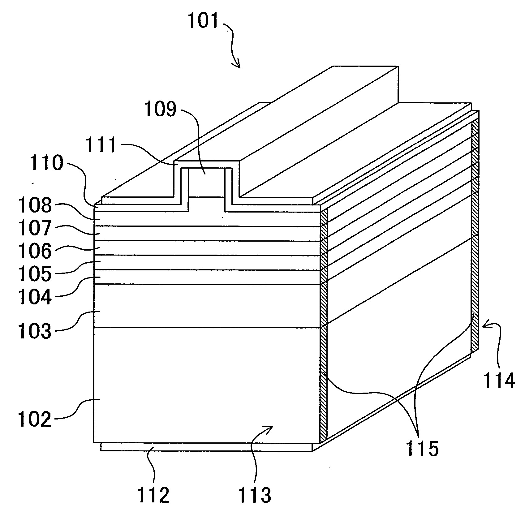
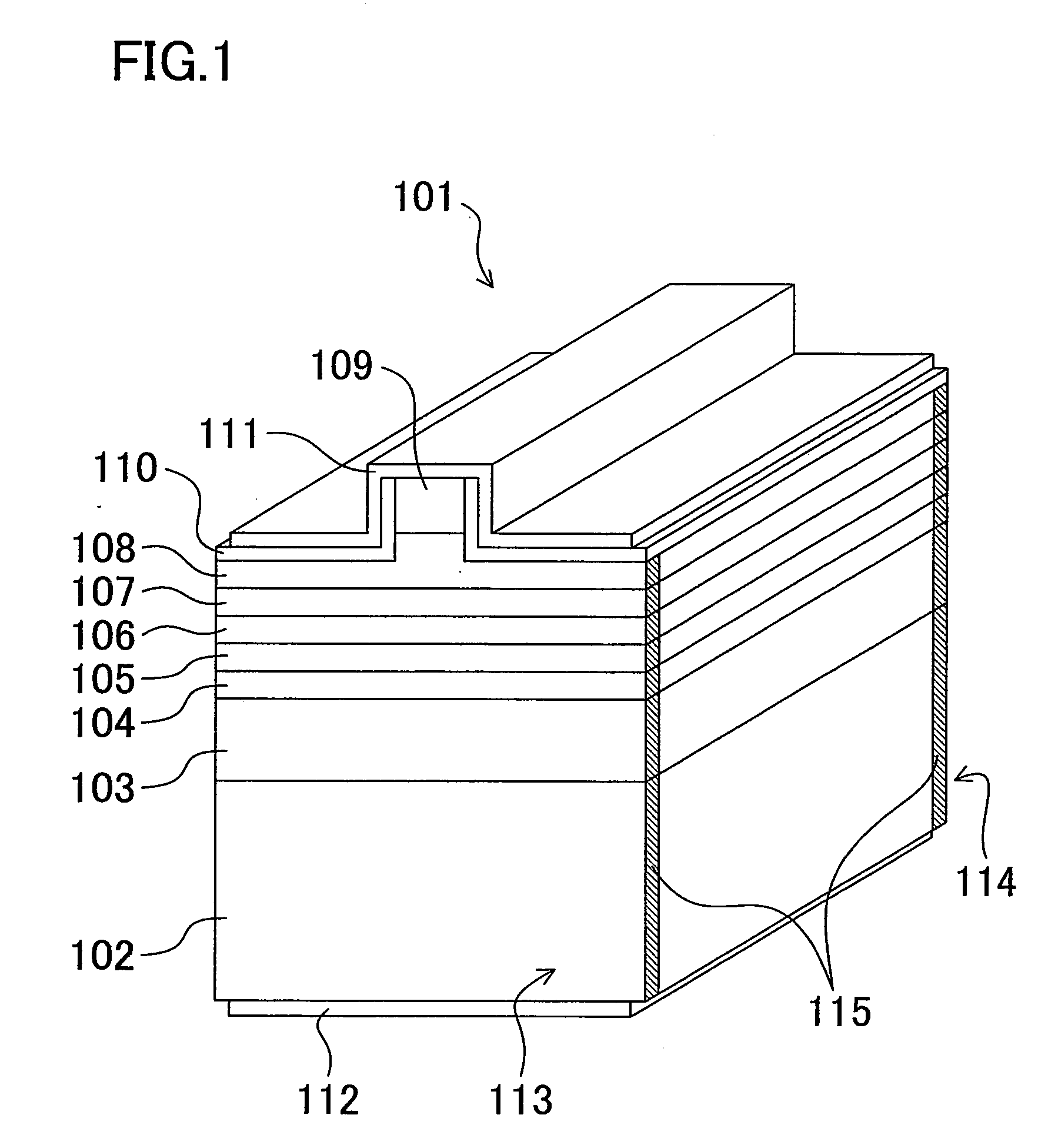
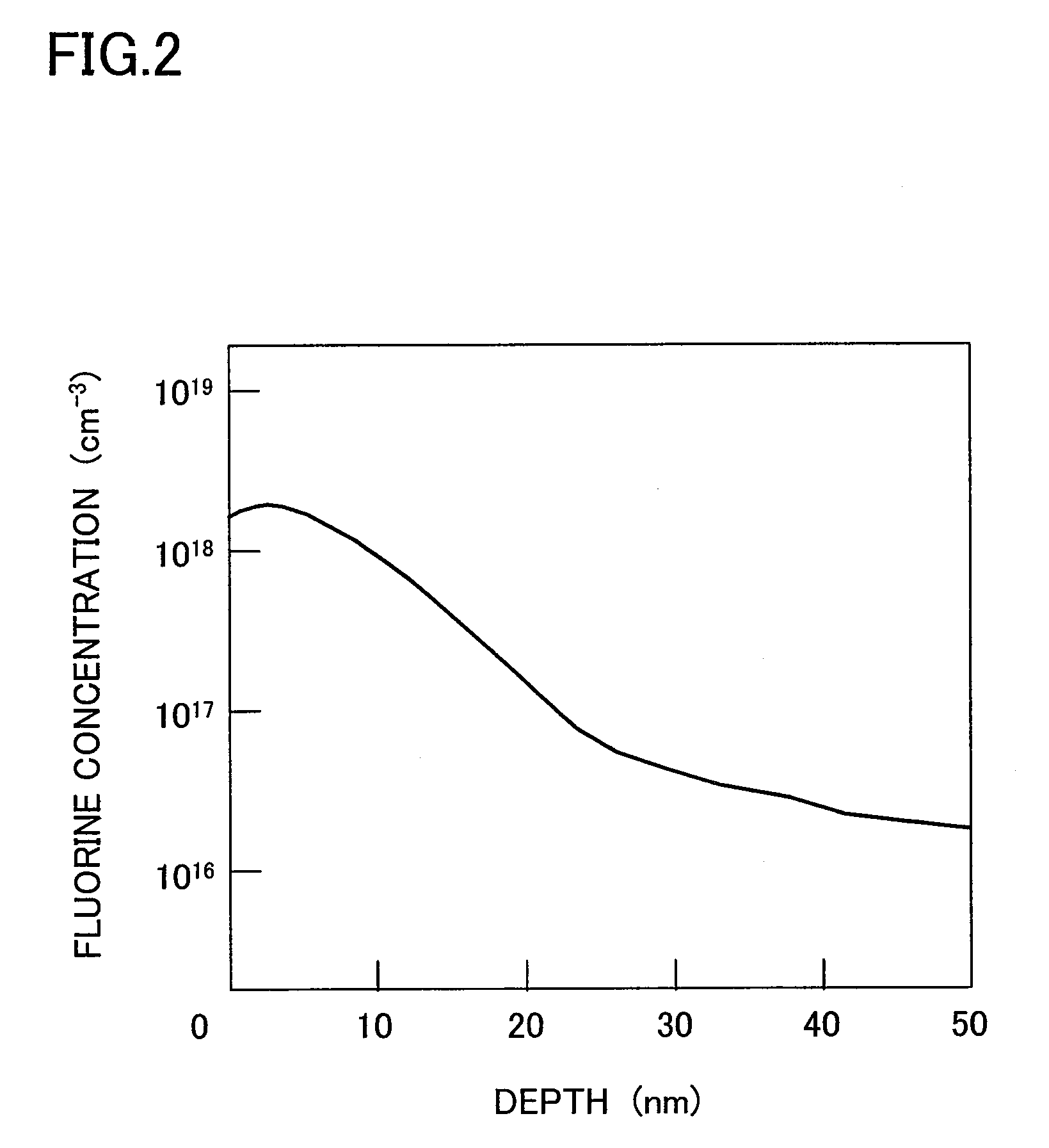
[0106]FIG. 1 is a perspective view of a semiconductor laser according to Embodiment 1 of the invention. The semiconductor laser 101 has an epitaxial layer structure in which a first cladding layer 103 made of Si-doped n-type (first conductivity type) Al0.05Ga0.95N (with a thickness of 1 μm and a carrier concentration of 5×1017 cm−3), a first guiding layer 104 made of Si-doped n-type GaN (with a thickness of 100 nm and a carrier concentration of 5×1017 cm−3), an active layer 105 of a multiple quantum well of a non-doped In0.08Ga0.92N well layer (with a thickness of 3 nm) and a GaN barrier layer (with a thickness of 8 nm), a second guiding layer 106 made of non-doped GaN (with a thickness of 100 nm), an overflow suppressing layer 107 made of Mg-doped p-type (second conductivity type) Al0.15Ga0.85N (with a thickness of 10 nm and a carrier concentration of 1×1019 cm−3), a second cladding layer 108 made of Mg-doped p-type Al0.1Ga0.9N / GaN superlattice (with a thickness of 500 nm) and a co...
embodiment 2
[0121]Embodiment 2 of the invention will now be described with reference to FIGS. 6A and 6B. In this embodiment, the active layer 105 of the semiconductor laser 101 shown in FIG. 1 is formed as an undoped GaN bulk (with a thickness of 100 nm) instead of the multiple quantum well. Also, the first guiding layer 104, the second guiding layer 106 and the overflow suppressing layer 107 are not formed. Apart from this, the semiconductor laser of this embodiment has a similar structure to that of Embodiment 1 and is fabricated in a similar fabrication method to that described in Embodiment 1.
[0122]Also in this embodiment, a window region for suppressing the COD is formed by introducing an impurity element with higher electronegativity than nitrogen, which will be described with reference to FIGS. 6A and 6B. FIGS. 6A and 6B respectively correspond to FIGS. 4A and 4B mentioned in Embodiment 1, and are energy band diagrams of a first cladding layer 601, an active layer 602 and a second claddi...
embodiment 3
[0126]Embodiment 3 of the invention will now be described with reference to FIG. 7. This embodiment describes a fabrication method, in which the end face treatment is performed by a method other than the plasma processing, i.e., exposing an end face to plasma including an impurity element with higher electronegativity than nitrogen. Procedures other than the end face treatment are performed in the same manner as in Embodiment 1, and an impurity element with higher electronegativity than nitrogen such as fluorine is ion implanted through a resonator end face of a semiconductor laser having been processed into the shape of a bar having a resonator end face exposed through the cleavage. FIG. 7 corresponds to FIG. 2 mentioned in Embodiment 1 and shows the profile along the depth direction of the ion implanted fluorine. In this embodiment, the peak implantation amount is 6×1018 cm−3 and the implantation depth is 170 nm, and the implantation amount and the implantation depth of the ion im...
PUM
 Abstract
Description
Claims
Application Information
 - R&D
- Intellectual Property
- Life Sciences
- Materials
- Tech Scout
- Unparalleled Data Quality
- Higher Quality Content
- 60% Fewer Hallucinations
Browse by: Latest US Patents, China's latest patents, Technical Efficacy Thesaurus, Application Domain, Technology Topic, Popular Technical Reports.
© 2025 PatSnap. All rights reserved.Legal|Privacy policy|Modern Slavery Act Transparency Statement|Sitemap|About US| Contact US: help@patsnap.com


