Air compressor

a compressor and air technology, applied in the direction of positive displacement liquid engines, piston pumps, gearing, etc., can solve the problems of encouraging belt damage, racks may fail to tilt during belt adjustment, etc., to prevent deformation of electric-motor bases, reduce the moment, and maintain good alignment

Inactive Publication Date: 2009-05-28
HITACHI IND EQUIP SYST CO LTD
View PDF8 Cites 8 Cited by
  • Summary
  • Abstract
  • Description
  • Claims
  • Application Information

AI Technical Summary

Benefits of technology

[0019]According to the aspects of the invention, a tilt axis of the electric-motor base can be disposed below the output shaft of the electric motor placed on the electric-motor base. This accordingly enables to reduce the moment about the tilt axis of the electric mo

Problems solved by technology

If such a phenomenon occurs, a displacement is observed on the rotation surface between the pulley of the electric motor and that of the compressor, and thus the alignment is lost between th

Method used


Image

  • Air compressor
  • Air compressor
  • Air compressor

Examples


Embodiment Construction

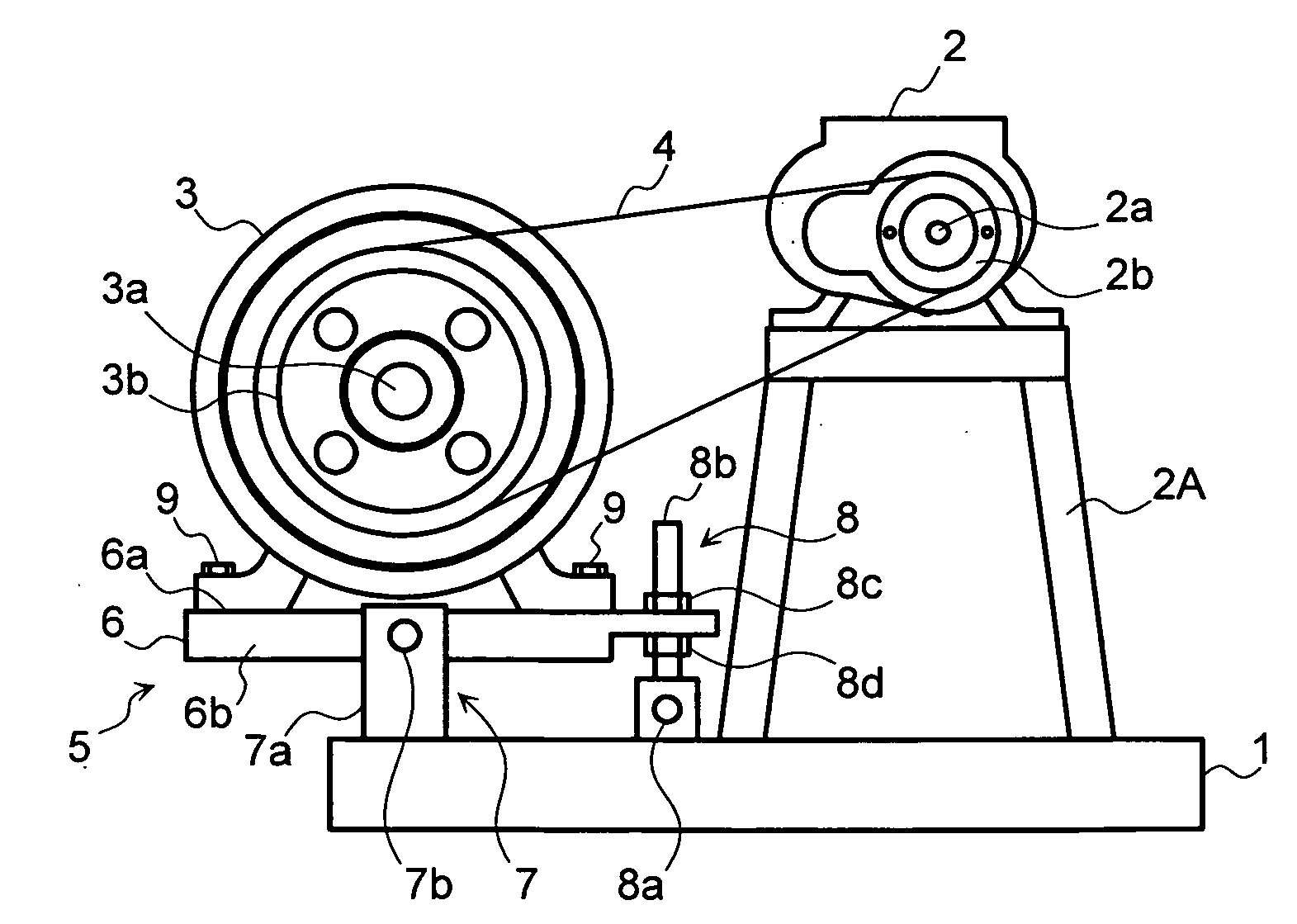
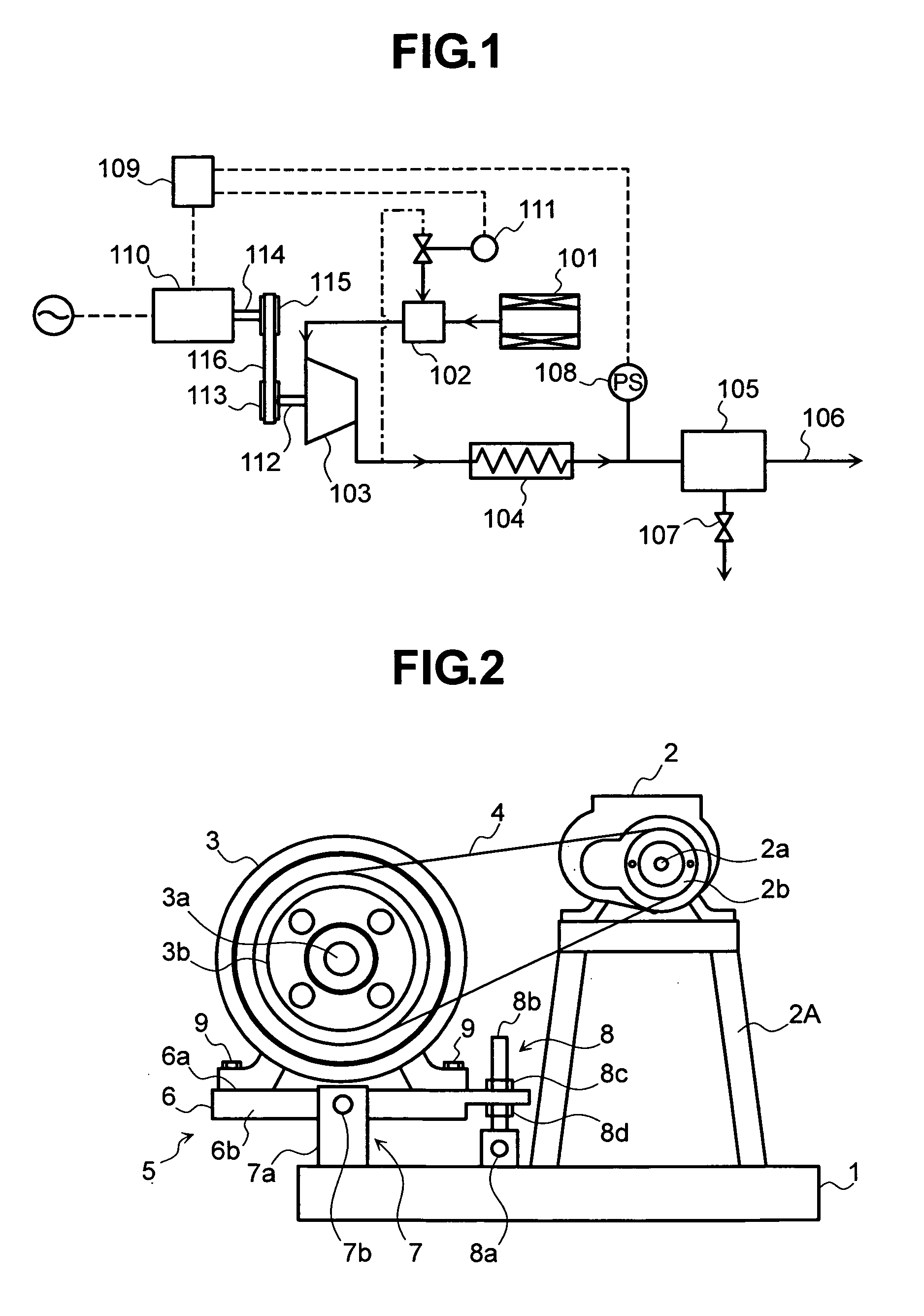
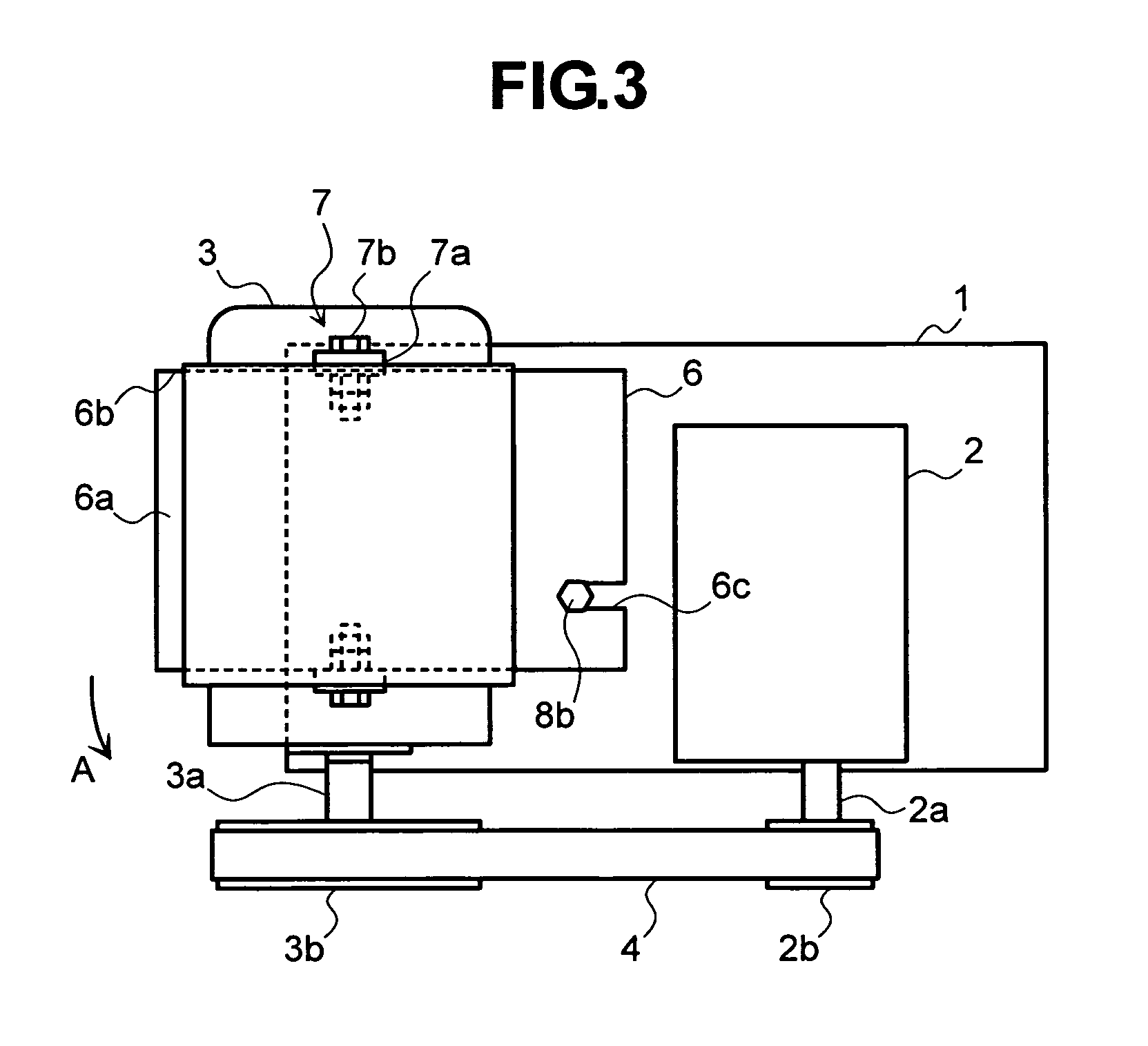
[0026]In the below, air compressors in embodiments of the invention are described by referring to the accompanying drawings.

[0027]FIG. 1 is a system diagram of an air compressor in an embodiment of the invention. In FIG. 1, air at atmospheric pressure, i.e., air flow for compression, is directed into a compressor body 103 via a suction filter 101 and a suction valve 102, and is compressed in the compressor body 103 down to a predetermined pressure value. The resulting air is cooled in a heat exchanger 104, is dehumidified by a dehumidifier 105, and then is discharged from a compressed air discharge port 106. The condensed moisture as a result of separation in the dehumidifier 105 is emitted outside after passing through a condensed water emission solenoid valve 107. The value of a pressure sensor 108 is used as a basis to determine in what load state the compressor body 103 is. The value of the pressure sensor 108 is also used by control unit 109 to control an electric motor 110 ove...


PUM


Abstract

Provided is an air compressor that can keep good alignment between pulleys 2b and 3b respectively of a compressor body and an electric motor, and a drive belt 4 placed thereacross.
Between a base 1 and the electric motor 3, an adjustment mechanism 5 is provided for adjusting the tension of the drive belt 4 by changing the relative position between the compressor body 2 and the electric motor 3. The adjustment mechanism 5 is provided with an electric-motor base 6 for supporting the electric motor, a support unit 7 that supports the electric-motor base 6 to allow a tilting axis thereof to be able to tilt at a position lower of an output shaft of the electric motor, and fixing unit 8 provided between an end of the electric-motor base 6 and the base 1 for fixing the electric-motor base 6 in a tilting state.

Description

CLAIM OF PRIORITY[0001]The present application claims priority from Japanese application serial no. JP2007-307962, filed on Nov. 28, 2007, the content of which is hereby incorporated by reference into this application.BACKGROUND OF THE INVENTION[0002]1. Field of the Invention[0003]The present invention relates to an air compressor that transmits the rotation of an electric motor to a compressor disposed in line using a drive belt placed across pulleys and, more specifically, to an air compressor that can adjust the tension of a drive belt placed across an electric motor and a compressor driven by the electric motor.[0004]2. Description of the Related Art[0005]In an air compressor whose compressor body is to be driven by the rotation of an electric motor, a transmission mechanism using coupling, gear, and belt and pulley, or others has been generally used as means for transmitting the rotation of the electric motor to the compressor body. The mechanism with coupling is of a configura...

Claims


Application Information

Patent Timeline
IPC IPC(8): F04D25/06F16H7/08
CPCF04D29/661F04D25/0606
Inventor SAKAGUCHI, TOMOTAKEKAMIYA, YUJICHIBA, KEITOKADO, TOMOYUKI
Owner HITACHI IND EQUIP SYST CO LTD
Why Eureka
Try Eureka