RNA Detection Method
a detection method and detection method technology, applied in the field of rna detection method, can solve the problems of inability to achieve satisfactory performance of the technique, time-consuming and difficult treatment operation steps for the use of any of these products, and the labor-intensive rt-pcr method, etc., to achieve the effect of simple and rapid manner
- Summary
- Abstract
- Description
- Claims
- Application Information
AI Technical Summary
Benefits of technology
Problems solved by technology
Method used
Image
Examples
first embodiment
[0106]FIG. 2 is a flow chart showing procedures of the RNA detection method as a first embodiment. FIG. 3A to FIG. 3C and FIG. 4A to FIG. 4D are drawings schematically showing reaction proceeded in the reaction space of the carrier, according to the flow chart shown in FIG. 2.
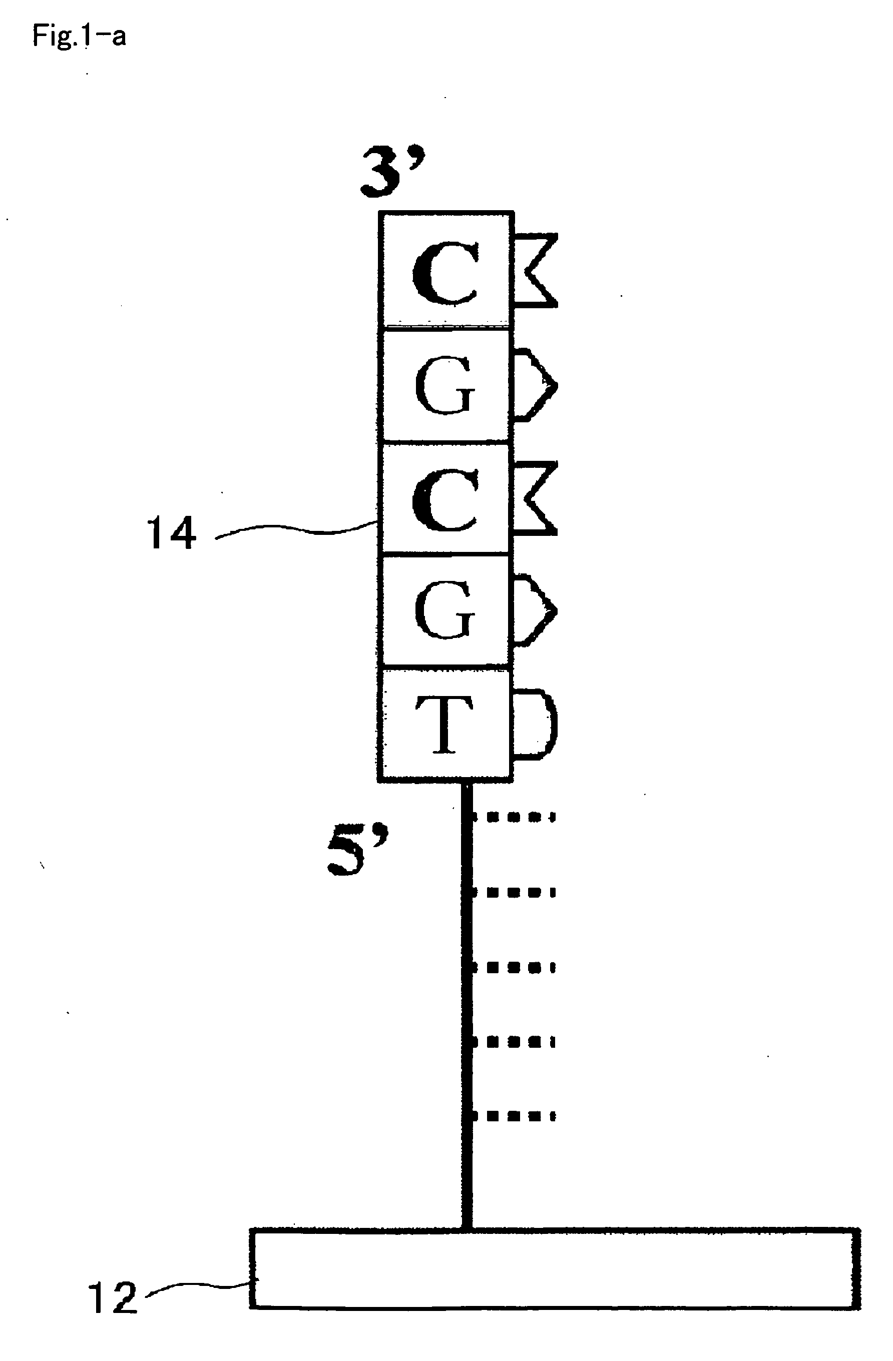
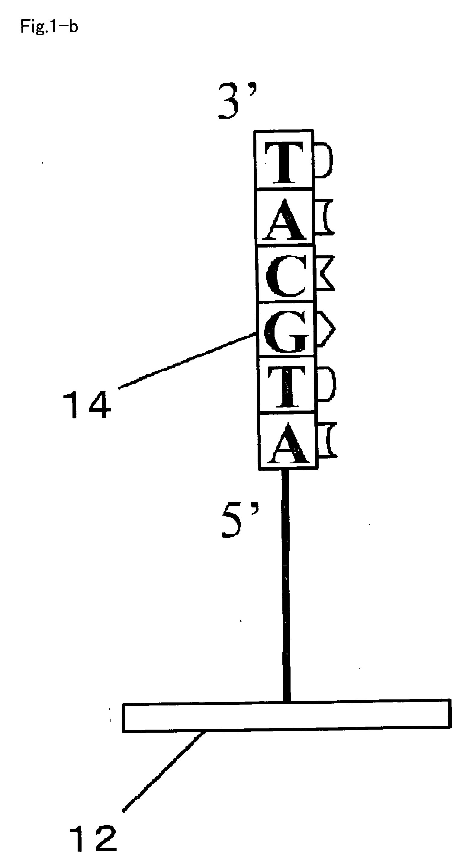
[0107]The RNA detection method includes a first step introducing a sample 22 which contains a target sample, which is typically cell lysate of target cells, an enzyme system for DNA chain extension, and nucleotide monomers into a reaction space 20 provided on the carrier 12 (substrate, for example) (step S10), and allowing DNA chain extension reaction ahead of the immobilized DNA primer (primer 14) to proceed using an RNA chain 16 contained in the target sample as a template (steps S20, S30); and a second step detecting a DNA chain 18 obtained by the extension reaction (step S50).
[0108]As shown in FIG. 2, in step S10, the sample 22 containing the cell lysate, the enzyme system for DNA chain extension, and the n...
second embodiment
[0121]FIG. 5 is a flow chart showing procedures of the RNA detection method as a second embodiment. FIG. 6A to FIG. 6D and FIG. 7A to FIG. 7E are drawing schematically showing reactions proceeded in the reaction space of the substrate, according to the flow chart shown in FIG. 5.
[0122]The RNA detection method includes a first step introducing, into the reaction space 20 provided on the carrier 12, a sample 22 containing the target sample, which is typically cell lysate of target cells, an enzyme system for DNA chain extension and nucleotide monomers (step S110), and allowing a DNA chain extension reaction to proceed ahead of the immobilized DNA primer (primer 14), while using an RNA chain 16 contained in the target sample as a template, to thereby form a cDNA chain 18 (steps S120, S130); a second step decomposing the RNA chain 16 in the reaction system 20, after the DNA chain extension reaction (step S140); a third step introducing, into the reaction system containing the cDNA chain...
third embodiment
[0134]FIG. 8 is a flow chart showing procedures of the RNA detection method as a third embodiment. FIG. 9A to FIG. 9D and FIG. 10A to FIG. 10E are drawings schematically showing the reactions proceeded in the reaction space of the carrier, according to the flow chart shown in FIG. 8.
[0135]The RNA detection method includes a first step introducing, into the reaction space 20 provided on the carrier 12, a sample 22 containing the target sample, which is typically cell lysate of target cells, an enzyme system for DNA chain extension and nucleotide monomers (step S210), and allowing a DNA chain extension reaction to proceed ahead of the immobilized DNA primer (primer 14), while using an RNA chain 16 contained in the target sample as a template, to thereby form a cDNA chain (steps S220, S230); a second step decomposing the RNA chain 16 in the reaction system containing the above-described cell lysate of the target cells, after the DNA chain extension reaction (step S240); a third step in...
PUM
| Property | Measurement | Unit |
|---|---|---|
| Fraction | aaaaa | aaaaa |
| Concentration | aaaaa | aaaaa |
| Hydrophilicity | aaaaa | aaaaa |
Abstract
Description
Claims
Application Information
 - R&D
- Intellectual Property
- Life Sciences
- Materials
- Tech Scout
- Unparalleled Data Quality
- Higher Quality Content
- 60% Fewer Hallucinations
Browse by: Latest US Patents, China's latest patents, Technical Efficacy Thesaurus, Application Domain, Technology Topic, Popular Technical Reports.
© 2025 PatSnap. All rights reserved.Legal|Privacy policy|Modern Slavery Act Transparency Statement|Sitemap|About US| Contact US: help@patsnap.com


