Turbocompound engine drive

Inactive Publication Date: 2009-06-04
DAIMLER AG
View PDF1 Cites 16 Cited by
  • Summary
  • Abstract
  • Description
  • Claims
  • Application Information

AI Technical Summary

Benefits of technology

[0011]The freewheel in this case can be arranged in an especially advantageous way between the pump wheel gear, that is, the second gear and the pump wheel of the hydrodynamic clutch. In this way, the other gear of the reduction gear is not coupled during parti

Problems solved by technology

In the partial-load range of the internal combustion engine, the turbocompound engine drive would have a poorer efficiency compared with a drive train without a turbocom

Method used


Image

  • Turbocompound engine drive
  • Turbocompound engine drive

Examples


Embodiment Construction

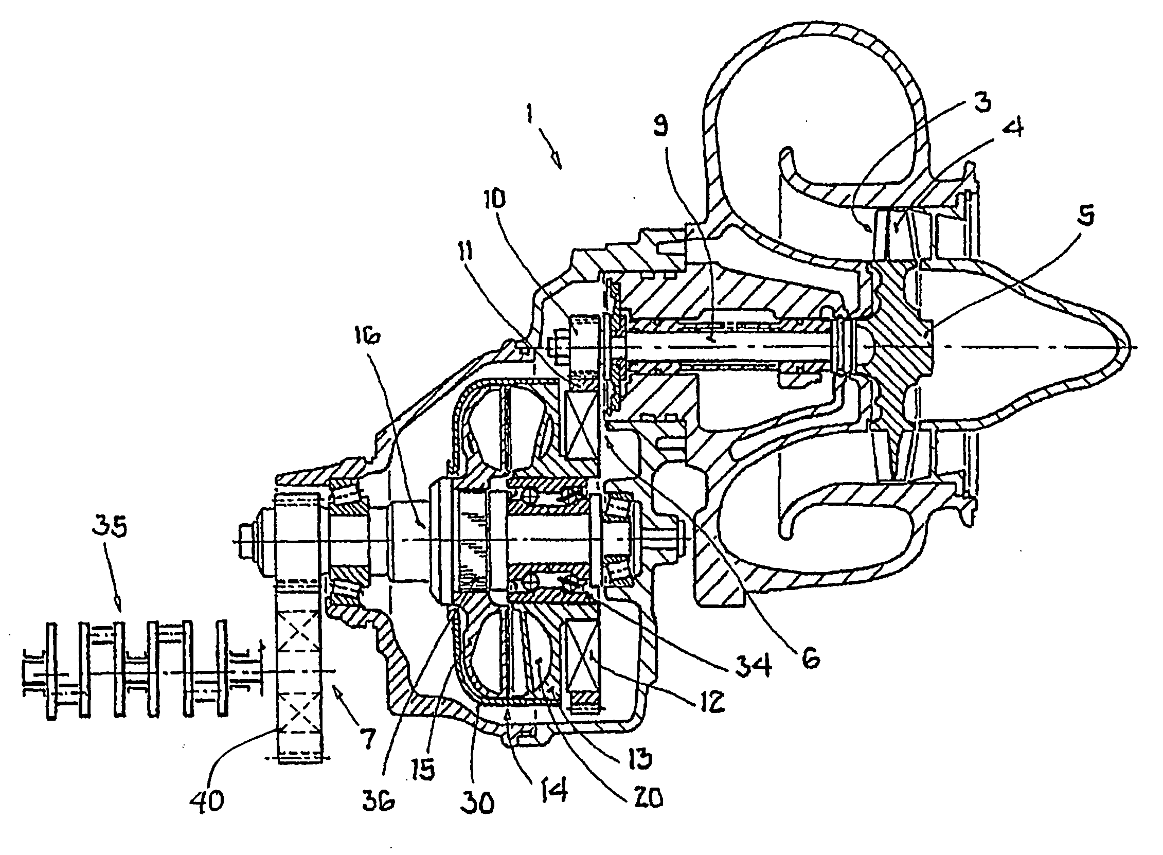
[0015]A turbocompound engine drive train 1 presented in the FIGURE, is not shown in full detail, It includes also a driving engine, for example, a diesel engine with a crankshaft 35, a transmission and a driven shaft.

[0016]From an exhaust gas manifold of the engine, the exhaust gas flow is directed to a turbocharger, which is not shown, for engine charging and therefore for improving the overall efficiency of the drive train.

[0017]The exhaust gas of this diesel engine then is conducted to an exhaust gas power turbine 3. In the turbine, the exhaust gas is directed past blade 4 of an exhaust gas power turbine wheel 5 of the exhaust gas power turbine 3.

[0018]As a result of the exhaust gas flow, the exhaust gas power turbine wheel 5 rotates at a speed of up to 60000 RPM. The speed is reduced via two consecutive reduction gears 6, 7 to the speed range of a crankshaft 2 of the diesel engine, which on average is only about 2000 RPM. For this purpose, the exhaust gas power turbine wheel 5 i...


PUM


Abstract

In a turbocompound engine drive including an engine with a crankshaft, an exhaust gas turbine operatively connected to the crankshaft via a reduction gear structure and a hydrodynamic clutch providing together for a power transmission path between the engine a freewheel is integrated into the power transmission path between the turbine and the crankshaft of the engine for disconnecting the turbine from the engine when the turbine speed is lower than the comparable engine speed to prevent the turbine from being driven by the engine.

Description

[0001]This is a Continuation-In-Part Application of pending International patent application PCT / EP2007 / 004367 filed May 16, 2008 and claiming the priority of German patent application 10 2006 028 235.3 filed Jun. 20, 2006.BACKGROUND OF THE INVENTION[0002]The invention relates to a turbocompound engine drive including an engine with a crankshaft and an exhaust gas turbine connected to the crankshaft of the engine via a reduction gear and a hydrodynamic clutch.[0003]A turbocompound engine drive is already known for example, from DE 103 19 748 A1. In this turbocompound engine drive, an exhaust gas power turbine is provided, which drives a crankshaft of the engine via a hydrodynamic clutch. The blades of the pump wheel and of the turbine wheel of this hydrodynamic clutch are inclined in relation to their longitudinal axis and are arranged with free play in relation to each other, wherein the blades of the primary wheel are inclined in the direction of rotation and the blades of the sec...

Claims


Application Information

Patent Timeline
IPC IPC(8): F02G3/00
CPCY02T10/163F02B41/10Y02T10/12
Inventor EBERLE, FRANKLAUFER, THOMAS
Owner DAIMLER AG
Why Eureka
Try Eureka