Device with detection by suspended piezoresistive strain gauge comprising a strain amplifier cell

a strain gauge and strain amplifier technology, applied in the field of micro-components or nano-components, can solve the problems of lowering the quality factor, poor adaptation, and quality factor

Inactive Publication Date: 2009-06-04
COMMISSARIAT A LENERGIE ATOMIQUE ET AUX ENERGIES ALTERNATIVES
View PDF15 Cites 19 Cited by
  • Summary
  • Abstract
  • Description
  • Claims
  • Application Information

AI Technical Summary

Problems solved by technology

Yet, in the case of a miniaturisation of this type of sensor, for example in the context of forming NEMS (Nano Electro Mechanical Systems), these types of detection become problematic due to the very low measurement capacity in the case of an electrostatic detection, the difficulty of forming piezoresistive gauges by implantation, or the problem, in the case of piezoelectric gauges, linked to the deposition of a piezoelectric material on the resonator, leading to a lowering of the quality factor.
This implies:an important restriction in the possible designs of sensors, notably in the case of integrated bi-axial sensors such as inertial sensors,a poor adaptation to sensors formed using surface technology,a poor adaptation to “ultra-miniaturised” sensors, such as NEMS, in so much as it is difficult to define, with a sufficient precision and without adding mechanical strains due to the metallisations on the proof body, the doping and connector zones fo

Method used


Image

  • Device with detection by suspended piezoresistive strain gauge comprising a strain amplifier cell
  • Device with detection by suspended piezoresistive strain gauge comprising a strain amplifier cell
  • Device with detection by suspended piezoresistive strain gauge comprising a strain amplifier cell

Examples


first embodiment

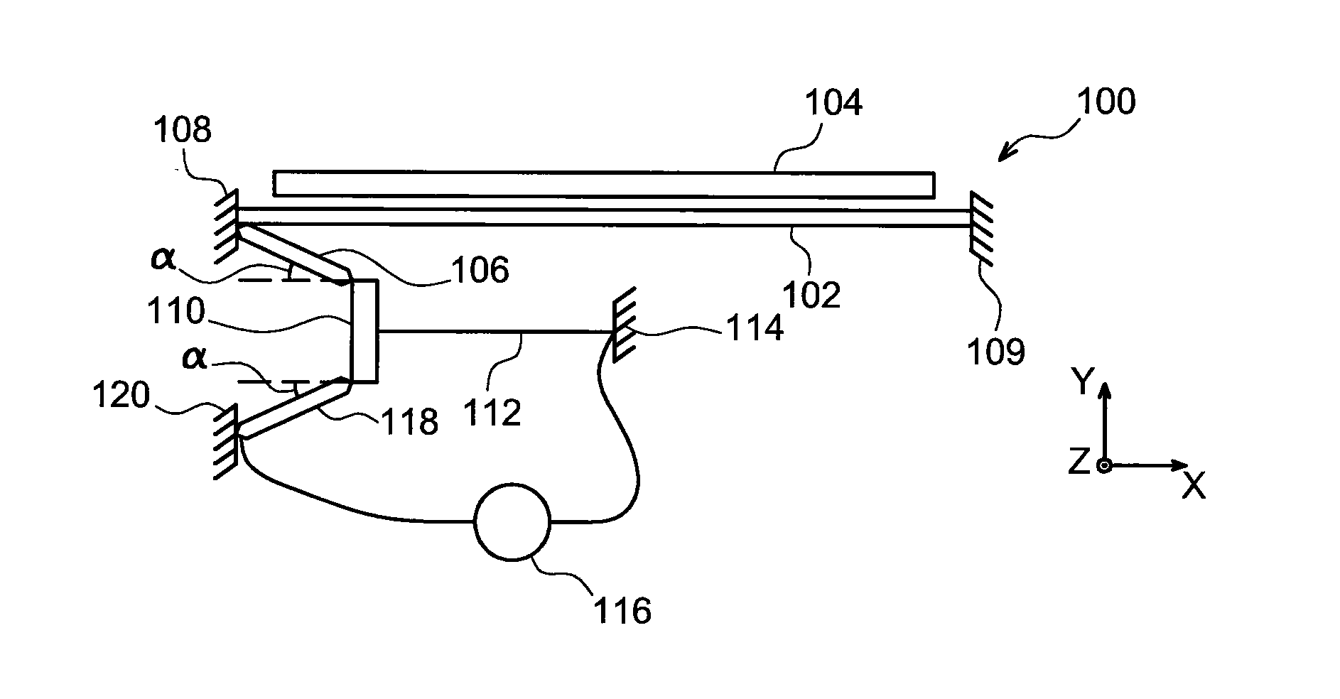
[0083]Reference will firstly be made to FIG. 1, which represents a microcomponent 100 according to a

[0084]In this first embodiment, the microcomponent 100 is a resonator, of MEMS or NEMS type. The resonator 100 comprises a resonant element 102, or resonant structure, for example of beam type, flexing in a plane (x,y) corresponding to the plane of a substrate (not represented) from which is formed the resonator 100. In an alternative embodiment, the resonant element 102 may be of diapason type, in other words formed by at least two beams linked to each other at the level of one of their ends. The resonant element 102 is intended to be excited by excitation means 104, for example an excitation electrode. These excitation means 104 may be of capacitive, and / or piezoelectric, and / or magnetic and / or thermoelastic type.

[0085]The resonant element 102 is joined, through the intermediary of a pivot link, to one end, known as second end, of a first rigid arm 106, near to a first embedment 108...

second embodiment

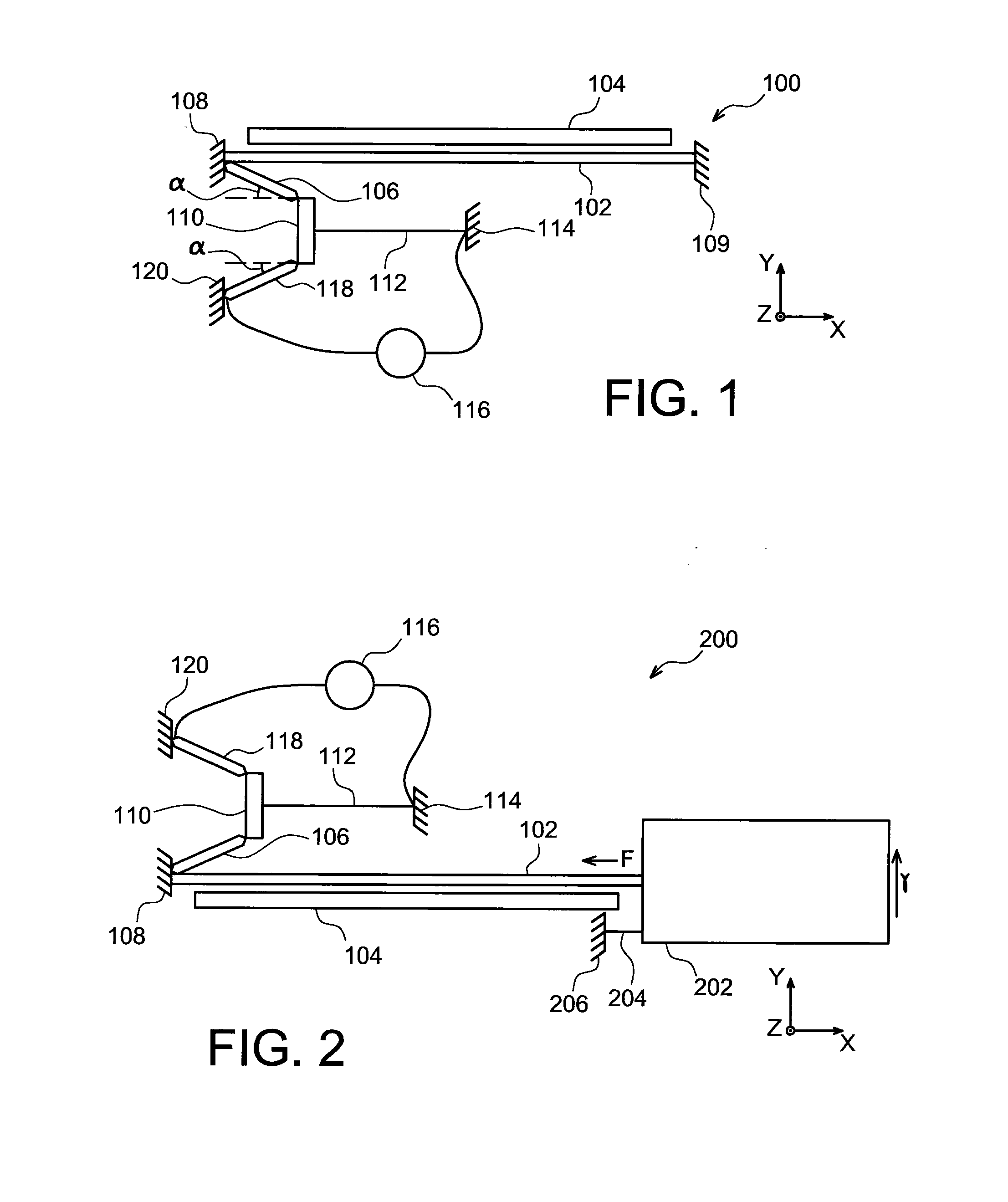
[0095]Reference will now be made to FIG. 2, which represents a microcomponent 200, here a resonant sensor, according to a

[0096]The resonant sensor 200, here of accelerometer type, comprises a resonant element 102 in which one of its ends is fixed to the substrate on which is formed the sensor 200, through the intermediary of a first embedment 108, and attached at the level of its other end to a seismic mass 202, in the vicinity of a hinge 204 linking the seismic mass 202 to a second embedment 206 to the substrate. The sensor 200 also comprises excitation means 104, for example electrostatic, here an electrode, of the resonant element 102, an amplifier cell formed by two rigid arms 106, 118 and a link element 110 linked to a first end of a suspended piezoresistive strain gauge 112 which is also linked, at the level of a second end, to a third embedment 114. The amplifier cell and the gauge 112 are arranged in the vicinity of the first embedment 108 of the resonant element 102. Finall...

third embodiment

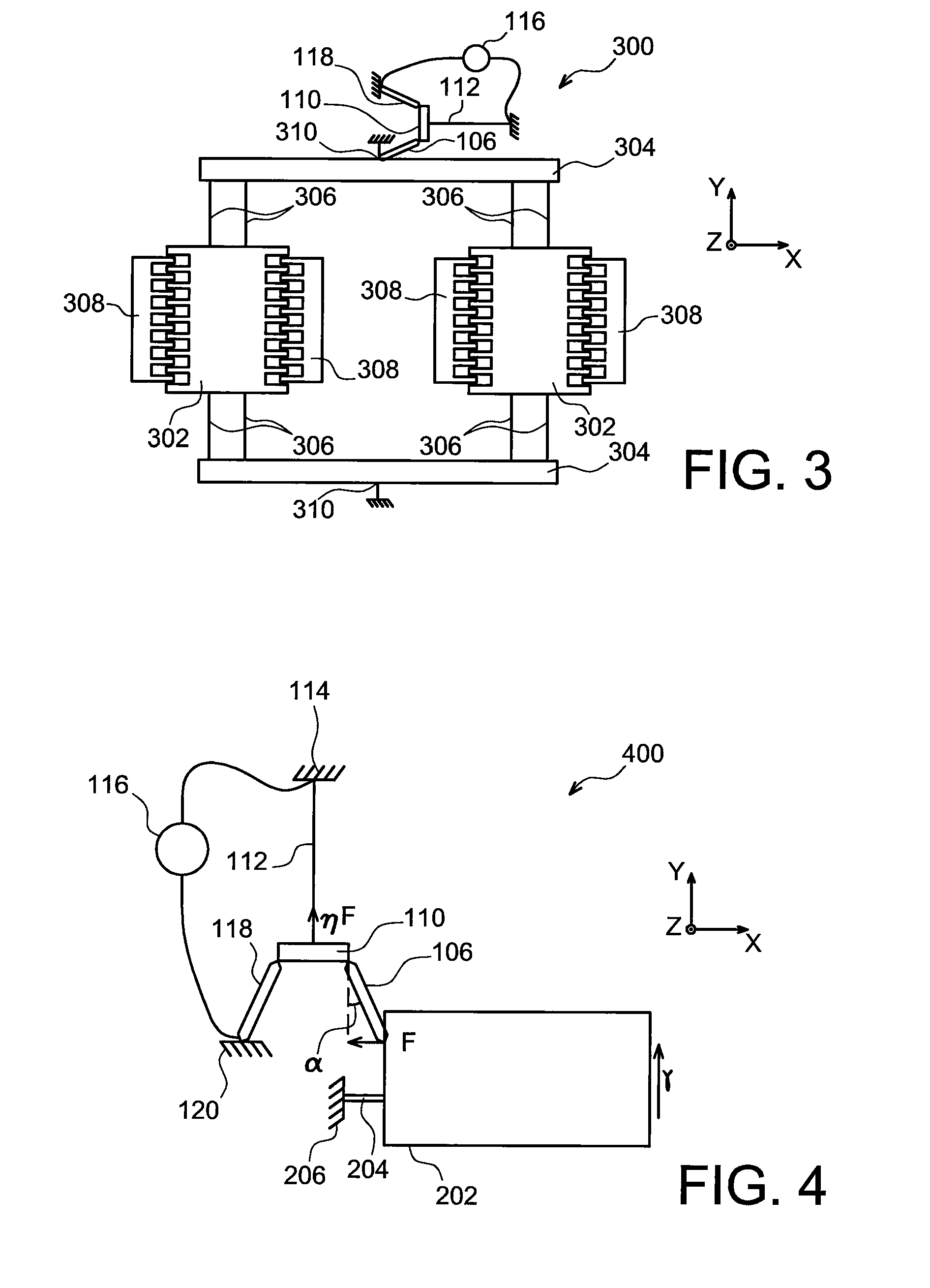
[0099]FIG. 3 represents a microcomponent 300, here a resonant gyrometer, according to a The gyrometer 300 comprises a substrate, not represented, and two mobile seismic masses 302 in the plane (x,y) of the substrate and capable of entering into vibration. Two link arms 304, here parallel to each other, are linked to the seismic masses 302 through the intermediary of flexing arms 306, the flexibility of which is sufficient to enable relative movements of the two seismic masses 302 in relation to the link arms 304, while being sufficiently rigid to transmit the movements of these two seismic masses 302 to the link arms 304. The link arms 304 and the flexing arms 306 here form a rectangular frame.

[0100]The gyrometer 300 also comprises excitation electrodes 308, for example in comb form, the fingers of which overlap with those of the seismic masses 302, capable of placing the seismic masses 302 in vibration in the plane (x,y), and especially in a direction parallel to the x vector. Oth...


PUM


Abstract

A device, with piezoresistive detection comprising at least:
    • a proof body on which an effort to be measured is exerted,
    • means of detecting a strain exerted by the proof body under the action of the effort, comprising at least one suspended piezoresistive strain gauge,
    • a strain amplifier cell comprising at least two rigid arms mechanically linked to each other by at least one link element at the level of a first of their ends, a second end of a first of the two rigid arms being mechanically linked to the proof body, a second end of a second of the two rigid arms being fixed to the substrate, the link element being mechanically linked to a first end of the suspended piezoresistive strain gauge.

Description

TECHNICAL FIELD AND PRIOR ART[0001]This document concerns the field of microcomponents or nanocomponents, particularly in silicon, for example inertial sensors, especially accelerometers, gyrometers or force sensors, resonant chemical sensors, and resonators.[0002]It finds application in varied fields, such as the automotive sector, mobile telephones or avionics, to form for example a time base or carry out a mechanical filtering.[0003]In a known manner, resonant sensors may be formed:[0004]either using volume technology, in which case the sensitive element of the sensor is formed over the whole thickness of a substrate in silicon or in quartz by humid etching steps,[0005]or using surface technology, in which case the silicon substrate is machined uniquely over a fraction of its thickness, for example between several micrometres and several tens of micrometres. The document “Resonant accelerometer with self-test”, by M. Aikele et al., Sensors and Actuators A 92 (2001), Elsevier, pag...

Claims


Application Information

Patent Timeline
IPC IPC(8): G01N3/08G01C19/56B81C99/00
CPCG01C19/574G01P15/123G01P15/097G01C19/5755
Inventor ROBERT, PHILIPPEHENTZ, SEBASTIEN
Owner COMMISSARIAT A LENERGIE ATOMIQUE ET AUX ENERGIES ALTERNATIVES
Why Eureka
Try Eureka