
Methods of Using Enhanced Wellbore Electrical Cables

a technology wellbore cables, which is applied in the direction of insulated conductors, borehole/well accessories, survey, etc., can solve the problems of corrosion and failure of armor wires, limited useful life of wellbore electric cables, and difficulty in removing oil or gas trapped therein, so as to minimize related equipment, the effect of eliminating the need for grease-packed flow tubes

Active Publication Date: 2009-06-11
SCHLUMBERGER TECH CORP
View PDF100 Cites 42 Cited by
  • Summary
  • Abstract
  • Description
  • Claims
  • Application Information

AI Technical Summary

Benefits of technology

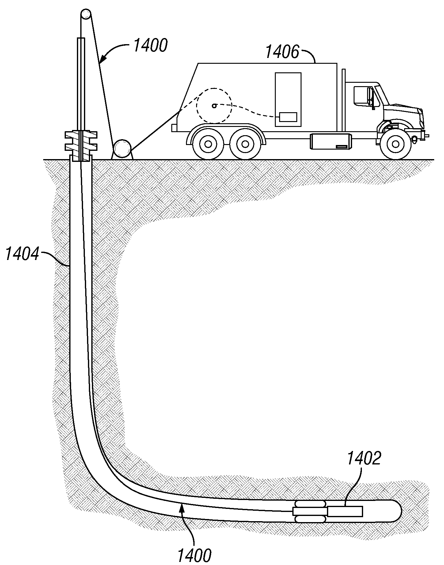
[0017]Alternatively, performing comprises performing a multi-stage fracturing operation. The cable may be inserted into a tubular and at least one pack-off is used to seal an annulus formed between the cable and the tubular. Alternatively, the operation is performed on a subsea formation, and wherein the cable is inserted into a tubular and whereby at least one pack-off is used to seal an annulus formed between the cable and the tubular. Alternatively, the operation is performed using a tractor attached to the cable, whereby the cable has reduced friction with the wellbore wall. Alternatively, the wellbore comprises a casing with a coated inner surface, whereby abrasion of the coating by the cable is reduced. Alternatively, the wellbore comprises a casing with a glass fiber inner lining, whereby abrasion of the inner lining by the cable is reduced.
[0023]Further disclosed herein are methods of using the embodiments of the cables in seismic and wellbore operations, including logging operations. The methods generally comprise attaching the cable with a wellbore tool and deploying such into a wellbore. The wellbore may or may not be sealed. In such methods, the cables of the invention may minimize or even eliminate the need for grease packed flow tubes and related equipment, as well as minimizing cable friction, wear on wellbore hardware and wellbore tubulars, and differential sticking. Also, the cables according to the invention may be spliced cables as used in wellbore operations wherein the wellbore is sealed.

Problems solved by technology

Formations generally comprising shale, which may also encapsulate oil-bearing formations, may have porosities much greater than that of sandstone or limestone, but, because the grain size of shale is very small, it may be very difficult to remove the oil or gas trapped therein.
Commonly, the useful life of a wellbore electric cable is typically limited to only about 6 to 24 months, as the cable may be compromised by exposure to extremely corrosive elements, or little or no maintenance of cable strength members, such as armor wires.
A primary factor limiting wireline cable life is armor wire failure, where fluids present in the downhole wellbore environment lead to corrosion and failure of the armor wires.
While zinc protects the steel at moderate temperatures, it is known that corrosion is readily possible at elevated temperatures and certain environmental conditions.
Although the cable core may still be functional, it is generally not economically feasible to replace the armor wire, and the entire cable must be discarded.
Once corrosive fluids infiltrate into the annular gaps, it is difficult or impossible to completely remove them.
Even after the cable is cleaned, the corrosive fluids remain in interstitial spaces damaging the cable.
Once the armor wire begins to corrode, strength is quickly lost, and the entire cable must be replaced.
Armor wires in wellbore electric cables are also associated with several operational problems including torque imbalance between armor wire layers, difficult-to-seal uneven outer profiles, and loose or broken armor wires.
Because the armor wire layers have unfilled annular gaps or interstitial spaces, dangerous gases from the well can migrate into and travel through these gaps upward toward lower pressure.
As the wireline goes over the upper sheave at the top of the piping, the armor wires may spread apart, or separate, slightly and the pressurized gas is released, where it becomes a fire or explosion hazard.
Further, while the cables with two layers of armor wires are under tension, the inner and outer armor wires, generally cabled at opposite lay angles, rotate slightly in opposite directions, causing torque imbalance problems.
To create a torque-balanced cable, inner armor wires would have to be somewhat larger than outer armor wires, but the smaller outer wires would quickly fail due to abrasion and exposure to corrosive fluids.
Therefore, larger armor wires are placed at the outside of the wireline cable, which results in torque imbalance.
Armored wellbore cables may also wear due to point-to-point contact between armor wires.
While under tension and when cables go over sheaves, radial loading causes point loading between outer and inner armor wires.
This causes strength reduction, leads to premature corrosion and may accelerate cable fatigue failure.
Also, due to annular gaps or interstitial spaces between the inner armor wires and the cable core, as the wireline cable is under tension the cable core materials tend to creep thus reducing cable diameter and causing linear stretching of the cable as well as premature electrical shorts.
This bouncing motion creates rapidly changing tension and torque, which can cause several problems.
This type of design has several problems, such as, when the jacket is damaged, harmful well fluids enter and are trapped between the jacket and the armor wire, causing corrosion, and since damage occurs beneath the jacket, it may go unnoticed until a catastrophic failure.
Also, during wellbore operations, such as logging, in deviated wells, wellbore cables make significant contact with the wellbore surface.
The spiraled ridges formed by the cables' armor wire commonly erode a groove in the side of the wellbore, and as pressure inside the well tends to be higher than pressure outside the well, the cable is prone to stick into the formed groove.
Further, the action of the cable contacting and moving against the wellbore wall may remove the protective zinc coating from the armor wires, causing corrosion at an increased rate, thereby reducing the cable life.

Method used


Image

  • Methods of Using Enhanced Wellbore Electrical Cables
  • Methods of Using Enhanced Wellbore Electrical Cables
  • Methods of Using Enhanced Wellbore Electrical Cables

Examples


Embodiment Construction

[0044]Illustrative embodiments are described below. In the interest of clarity, not all features of an actual implementation are described in this specification. It will of course be appreciated that in the development of any such actual embodiment, numerous implementation-specific decisions must be made to achieve the developer's specific goals, such as compliance with system related and business related constraints, which will vary from one implementation to another. Moreover, it will be appreciated that such a development effort might be complex and time consuming but would nevertheless be a routine undertaking for those of ordinary skill in the art having the benefit of this disclosure.

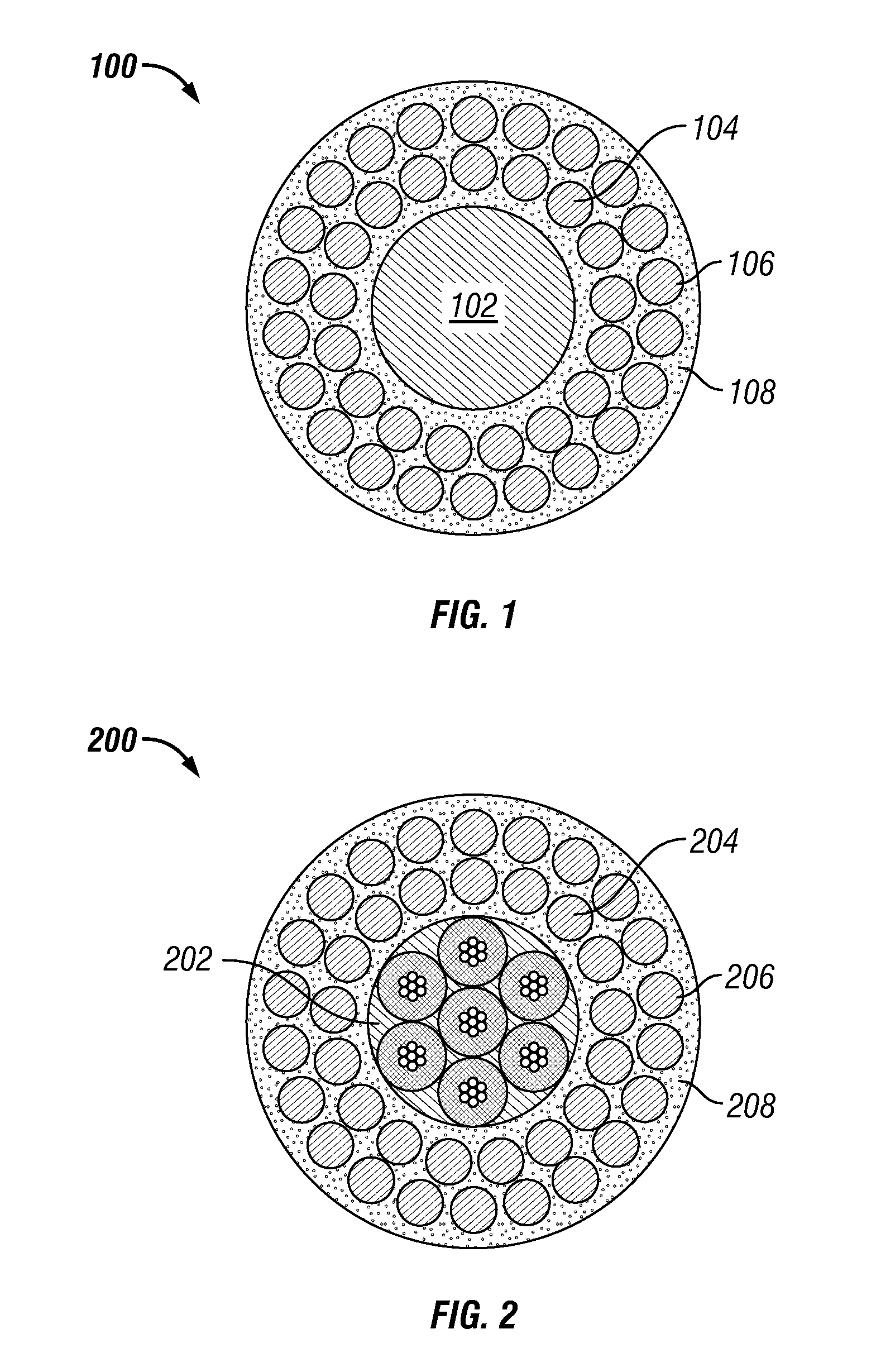
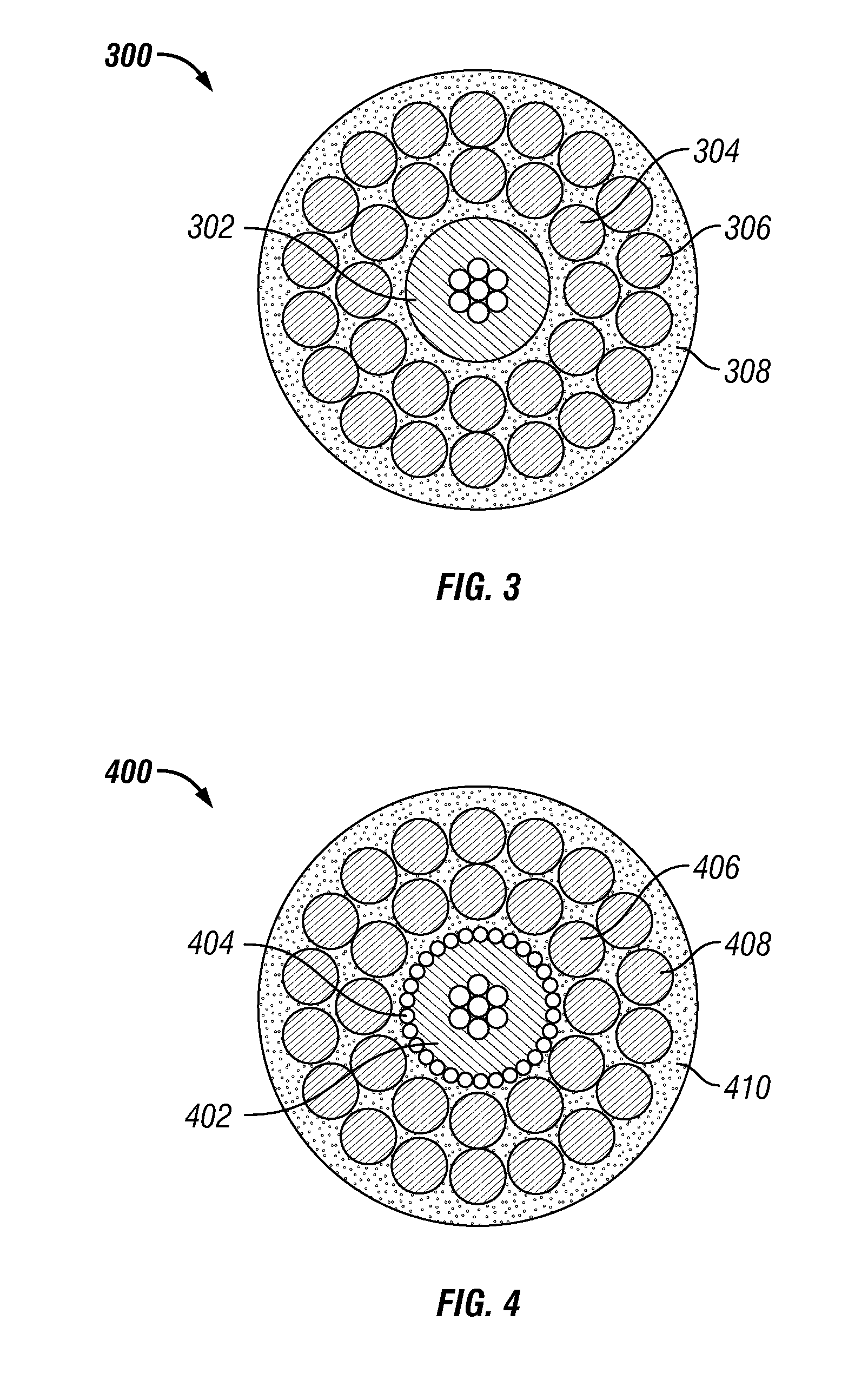
[0045]Embodiments of the invention relate to wellbore cables as well as uses thereof. In one aspect, the invention relates to an enhanced electrical cables used with devices to analyze geologic formations adjacent a wellbore, methods of manufacturing the same, and uses of the cables in seismic and...


PUM


Abstract

An embodiment of a method of deploying a cable into a wellbore penetrating a subterranean formation comprises providing a cable, wherein the cable comprises at least one insulated conductor, at least one armor wire layer surrounding the insulated conductor, a polymeric material disposed in interstitial spaces formed between armor wires forming the at least one armor wire layer, and interstitial spaces formed between the at least one armor wire layer and insulated conductor, the polymeric material forming a continuously bonded layer which separates and encapsulates the armor wires forming the at least one armor wire layer, and whereby the polymeric material is extended to form a smooth polymeric jacket around the at least one armor wire layer, introducing the cable into a wellbore and performing at least one operation in the wellbore utilizing the cable.

Description

CROSS-REFERENCE TO RELATED APPLICATION[0001]This application is a continuation-in-part application of prior copending application Ser. No. 11 / 813,755 entitled “Enhanced Wellbore Electrical Cables” filed Mar. 13, 2008, which was the PCT National Stage application of International Patent Application No. PCT / IB2006 / 050119, which claims priority to application Ser. No. 11 / 033,698 entitled “Enhanced Electrical Cables” filed Jan. 12, 2005, now U.S. Pat. No. 7,170,007, the entire disclosures of which are incorporated herein by reference and claims priority to the filing dates thereof.[0002]This application is entitled to the benefit of, and claims priority to, provisional patent applications 60 / 980,340 filed Oct. 16, 2007, and 60 / 985,771 filed Nov. 6, 2007 the entire disclosures of which are incorporated herein by reference.BACKGROUND OF THE INVENTION[0003]The statements in this section merely provide background information related to the present disclosure and may not constitute prior art...

Claims


Application Information

Patent Timeline
Patent Type & Authority Applications(United States)
IPC IPC(8): E21B19/08E21B19/00E21B43/26E21B47/00
CPCE21B17/206H01B7/046H02G1/10E21B19/22E21B47/121E21B47/00E21B47/0001D07B1/147E21B43/26E21B47/125E21B47/001
Inventor VARKEY, JOSEPHKIM, BYONG JUNSRIDHAR, GARUDFULIN, WAYNESAIT, NOOR F.BILLINGHAM, MATTHEWSBORDONE, ANDREA
Owner SCHLUMBERGER TECH CORP
Learn More