
Oxygen separation element and method

a technology of oxygen containing elements and separation elements, which is applied in the direction of fluid pressure measurement, liquid/fluent solid measurement, peptides, etc., can solve the problems of large power consumption of the device when in use, difficulty in simply applying an electrical current at one location of the current collector, and low flow of oxygen containing feed stream

Inactive Publication Date: 2009-06-11
PRAXAIR TECH INC
View PDF5 Cites 8 Cited by
  • Summary
  • Abstract
  • Description
  • Claims
  • Application Information

AI Technical Summary

Benefits of technology

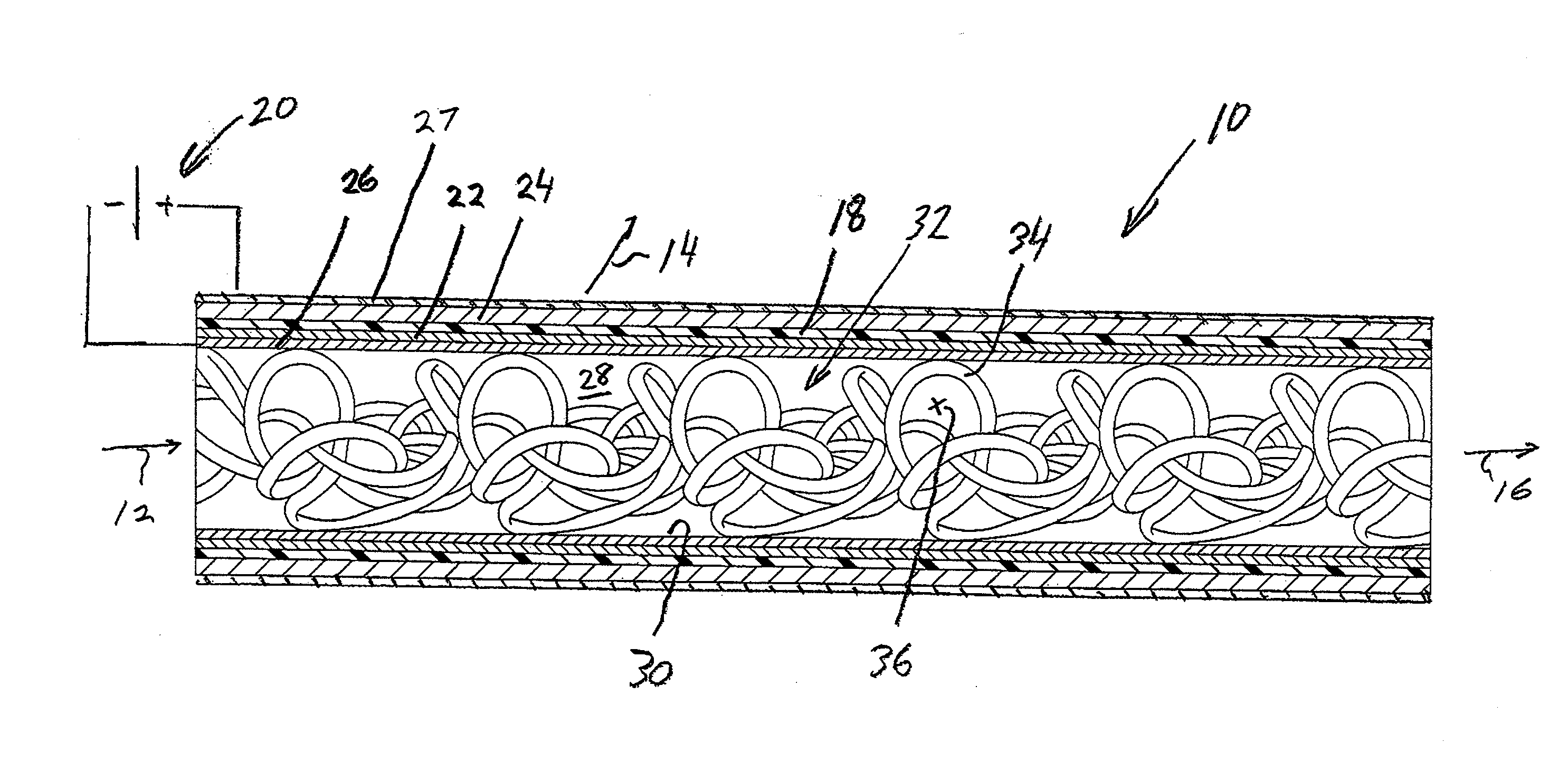
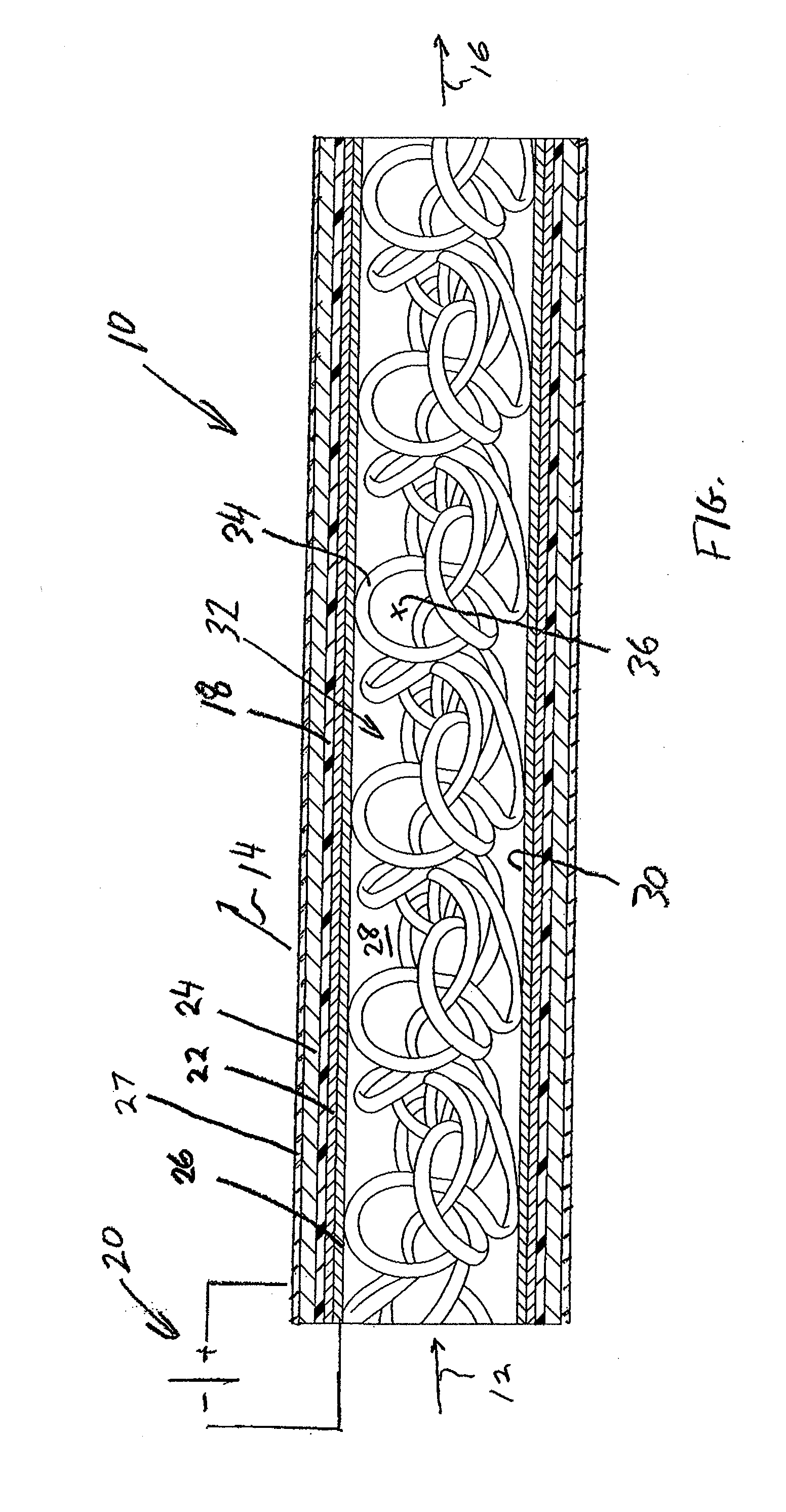
[0015]Preferably, the composite structure is of tubular configuration and the elongated, electrically conductive insert is an irregular, mesh of wire having loops of wire in contact with the inner surface. The oxygen containing feed stream in any aspect of the present invention can contain no more than five percent by volume of oxygen. As such, the electrically driven oxygen separation element can advantageously function within a device that is used to purify a feed stream that contains low amounts of oxygen.

Problems solved by technology

A problem with such devices particularly when in tubular form, is that the flow of the oxygen containing feed stream is typically at a sufficiently low rate that a boundary layer forms along the walls of the passageway formed by the current collector.
In order to separate the oxygen from the oxygen containing feed, particularly in the case of deoxo application, electrically driven oxygen separation elements can become sufficiently long such that it becomes difficult to simply apply an electrical current at one location of the current collector.
It is to be noted that it would be disadvantageous in such an arrangement to reverse the cathode in the anode electrodes in that the presence of such beads would produce a large pressure drop within the tube resulting in a larger power consumption of the device when in use.
A similar problem related to boundary layer effects near the inside of oxygen separation elements exists with respect to membrane filters.
The problem of utilizing such inserts with respect to electrically driven oxygen separation devices is that when placed in the passageway, they would result in a substantial pressure drop.

Method used


Image

  • Oxygen separation element and method
  • Oxygen separation element and method

Examples


Embodiment Construction

[0017]With reference to the FIGURE, an electrically driven oxygen separation element 10 is illustrated that is designed to be utilized within a device to separate oxygen from an oxygen containing feed stream 12 to produce an oxygen permeate 14. The separation of oxygen produces an oxygen depleted retentate 16. As known in the art, oxygen separation element 10 could be utilized within a device that has an insulated enclosure having heating elements to heat electrically driven oxygen separation element 10 to an operational temperature. A blower can be utilized to introduce oxygen containing feed stream 12 into oxygen separation element 10, all in a manner well known in the art.

[0018]Oxygen separation element 10 is of tubular configuration and is provided with an electrolyte 18 that can be yttrium stabilize zirconia, gadolinium doped ceria or other ionic conductors that when heated will exhibit oxygen ion conductivity when an electrical current produced by power source 20 is applied to...


PUM

PropertyMeasurementUnit
Percent by volumeaaaaaaaaaa
Lengthaaaaaaaaaa
Electrical conductivityaaaaaaaaaa

Abstract

An electrically driven oxygen separation element and method in which an oxygen containing feed stream is passed through a passageway of a composite structure having a current collector defining the passageway, a cathode electrode to ionize the oxygen, an electrolyte to transport oxygen ions to an anode to recombine into elemental oxygen. An elongated element, preferably formed of an irregular mesh of wire having loops in contact with the current collector can be provided to disrupt the flow directly adjacent the current collector and to help distribute the electrical current along the length of the current collector.

Description

FIELD OF THE INVENTION[0001]The present invention relates to an oxygen separation element and method in which the oxygen separation element is electrically driven and provided with a passageway through which an oxygen containing feed stream flows for separation of the oxygen and an elongated device in contact with a current collector forming the passageway for disrupting flow and for distributing the electrical current along the current collector.BACKGROUND OF THE INVENTION[0002]Electrically driven oxygen separation elements are used for separating oxygen from an oxygen containing feed. They are typically in tubular form, although other forms are possible such as flat plates having passageways between the plates. In an electrically driven oxygen separation element, an electrolyte is positioned between cathode and anode electrodes and an electrical current is applied to the electrodes. When an oxygen containing feed stream is passed along the cathode electrode, the oxygen ionizes and...

Claims


Application Information

Patent Timeline
IPC IPC(8): B01D57/02
CPCB01D53/22B01D53/326B01D63/06B01D2313/345C01B13/0248B01D2313/19B01D2256/12B01D2321/2016
Inventor VAN HASSEL, BART A.
Owner PRAXAIR TECH INC
Learn More