Apparatus for thermal control in the analysis of electronic devices

a technology of electronic devices and thermal control, applied in lighting and heating apparatus, instruments, nuclear engineering, etc., can solve the problems of significant reduction of numerical aperture (na), incompatibility with the optical characteristics of sils required to resolve features on duts, and substantial loss of image quality, so as to reduce friction between diamonds and reduce reflection losses , improve thermal contact and heat transfer

Inactive Publication Date: 2009-06-11
PRESTO ENG
View PDF28 Cites 2 Cited by
  • Summary
  • Abstract
  • Description
  • Claims
  • Application Information

AI Technical Summary

Benefits of technology

[0026]Consequently, the arrangement of the present invention can be used in conjunction with both air-gap and SIL lenses. Therefore, both global-imaging and pin-point measurements can be achieved using the same heat spreader by taking advantage of both the optical transparency and thermal conductivity characteristics of diamond.
[0027]Index matching fluid may be provided between the diamond and the silicon substrate of the DUT to eliminate reflection losses associated with light passing through the interface between dissimilar materials. In addition it is used in this invention to minimise friction between the diamond and the silicon substrate of the DUT and to improve the thermal contact and heat transfer. The index matching fluid may be sufficiently displaced from under the SIL to avoid affecting its optical performance.
[0028]In order to improve cooling of the SIL through the diamond, the SIL may be in intimate contact with the diamond heat spreader, and/or index matching fluid may be provided between the diamond and the SIL.
[0029]Analysis of the DUT is performed by connecting the DUT to a socket which allows for easy insertion and removal o

Problems solved by technology

However, viewing through the diamond heat spreader with a SIL causes a substantial loss of image quality and significantly reduces the improvement in numerical aperture (NA).
Such a heat spreader can be used satisfactorily to analyse a 90 nm feature on a DUT but is incompatible with the optical characteristics of SILs required to resolve features on DUTs which have a h

Method used


Image

  • Apparatus for thermal control in the analysis of electronic devices
  • Apparatus for thermal control in the analysis of electronic devices
  • Apparatus for thermal control in the analysis of electronic devices

Examples


Embodiment Construction

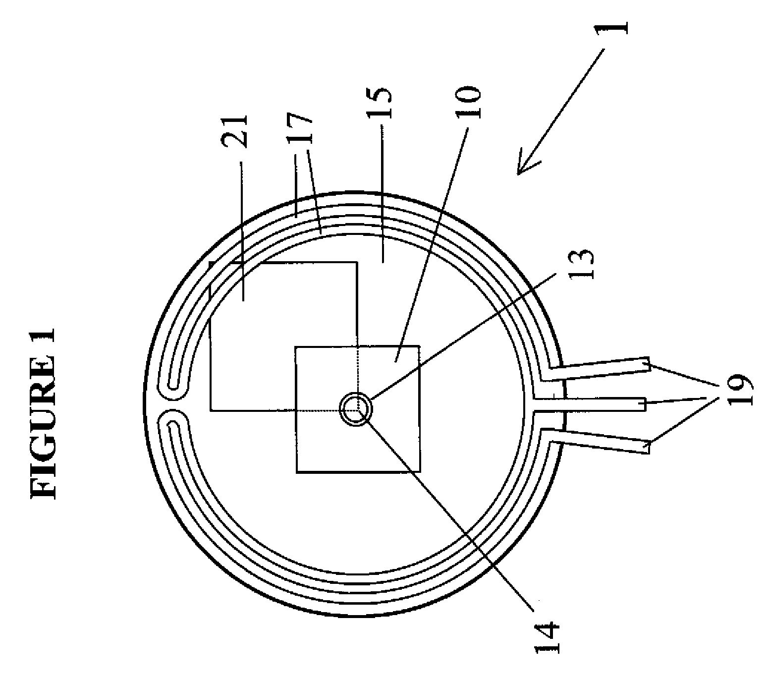
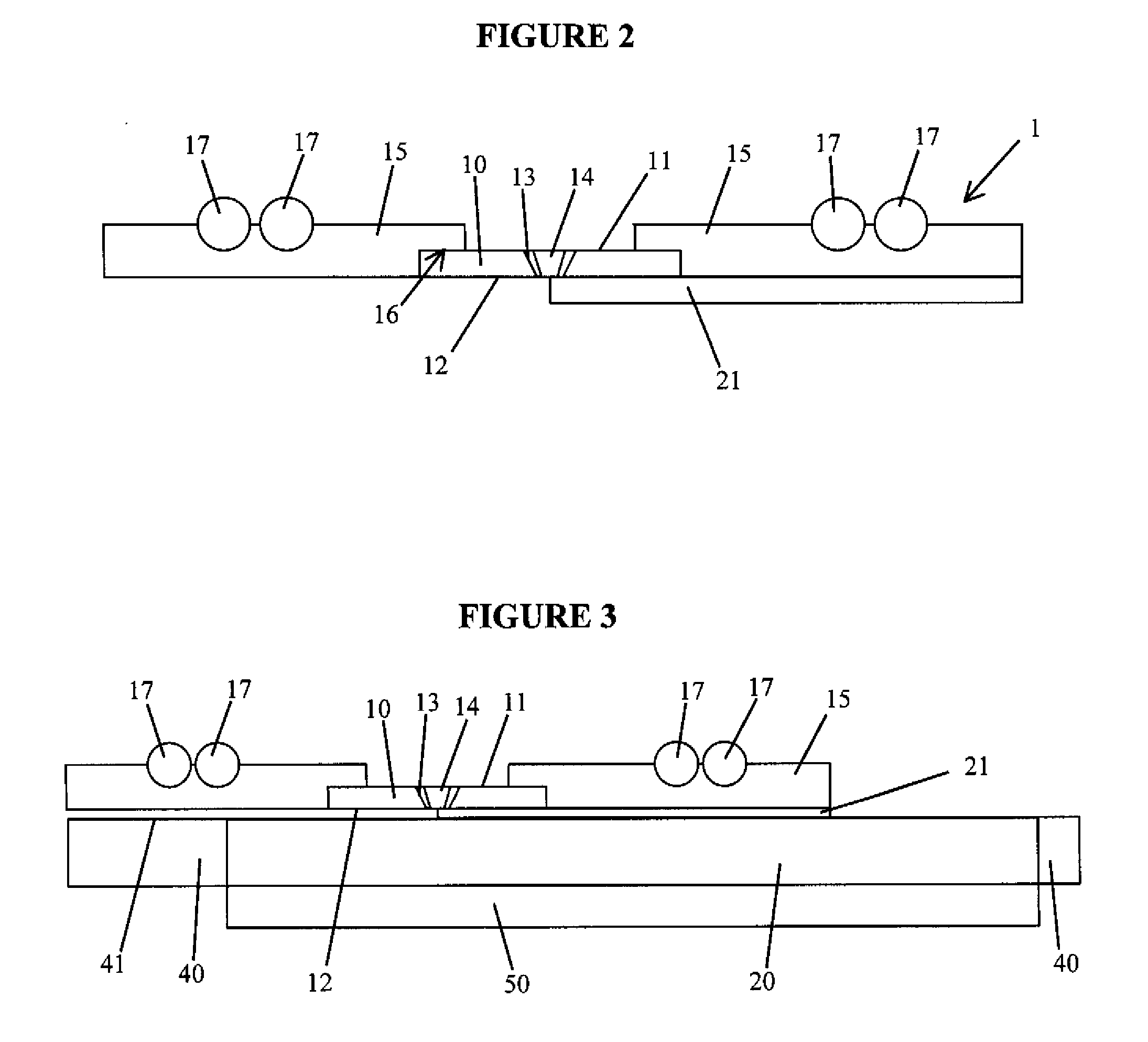
[0049]FIGS. 1 to 3 show a heat spreader 1 according to the present invention. The heat spreader 1 includes a sheet 10 of transparent diamond having a first surface 11 and a second surface 12 and an aperture 13 formed between the first surface 11 and the second surface 12. The diamond sheet 10 preferably has a thickness of 500 μm.

[0050]The aperture 13 is shaped and sized to accommodate a SIL 14. The SIL 14 typically has a diameter of 1-4 mm. Consequently, the aperture 13 typically has a diameter of approximately 1-4 mm.

[0051]In order to improve optical access to the SIL, the aperture 13 in the diamond sheet 10 is conical such that the area of the cross-section of the aperture 13 at the first surface 11 is larger than the area of the cross-section of the aperture 13 at the second surface 12. The walls of the aperture 13 are smooth in order to improve imaging through the diamond 10. The provision of the conical aperture 13 allows the same heat spreader to be used with SILs of different...


PUM


Abstract

A heat spreader comprising a sheet of transparent diamond with an aperture therein that accommodates a solid-immersion lens (SIL). The heat spreader may be mounted within a clamp which allows the heat spreader to move freely across the Device Under Test (DUT) whilst maintaining a very high degree of planarity and contact between the diamond and the silicon substrate of the DUT. The DUT is secured to its electrical interface with a low profile clamp, the DUT may be held within the clamp by a mechanism that applies a pressure to the sides of the DUT package.

Description

FIELD OF THE INVENTION[0001]The present invention relates to methods and apparatus for inspecting and analysing electronic devices such as microprocessors.BACKGROUND TO THE INVENTION[0002]One known method for inspecting and analysing electronic devices such as flip-chip packaged microprocessors involves optical or infrared probing of the electronic device. During probing, a device which includes a silicon substrate: the device under test (DUT), is powered normally and its response is measured through the back of the silicon substrate by analysing the phase shift in a laser probe. For example, a modulated 1.064 μm laser probe may be used. The laser illuminates the device through an air-gap lens or a solid-immersion-lens (SIL) and the reflected beam is collected through the same lens. As the DUT is under power, it generates a large amount of heat and needs to be actively cooled to maintain its temperature and prevent it from entering thermal runaway.[0003]In another known method, phot...

Claims


Application Information

Patent Timeline
IPC IPC(8): G21K7/00F28F7/00
CPCG01R31/311G01R31/2891
Inventor SAUK, FRANKCANFIELD, DANIEL C.HARSANY, JOHN JOSEPHYOST, III, WILLIAM JOSEPH
Owner PRESTO ENG
Why Eureka
Try Eureka