Eureka AIR delivers breakthrough ideas for toughest innovation challenges, trusted by R&D personnel around the world.

X-ray imaging matrix with light guides and intelligent pixel sensors, radiation or high energy particle detector devices that contain it, its fabrication process and its use

a technology of light guides and pixel sensors, applied in the direction of radiography controlled devices, instruments, television systems, etc., can solve the problems of difficult processing, uneven appearance of radiographies, and damage to the person handling,

Inactive Publication Date: 2009-06-11
UNIVERSITY OF MINHO
View PDF2 Cites 19 Cited by
  • Summary
  • Abstract
  • Description
  • Claims
  • Application Information

AI Technical Summary

Benefits of technology

The present invention relates to a method and apparatus for detecting digital x-ray images using a scintillating layer. The method and apparatus allow for the detection of high quality images with reduced radiation dosage and improved processing efficiency. The use of CMOS technology instead of CCD technology provides advantages such as lower power consumption, higher integration, and lower cost. The invention can be used in portable applications and in situations where conventional x-ray devices are not possible.

Problems solved by technology

The glass bases presented some disadvantages: they easily broke, possibly causing wounds to the person handling them; the processing was difficult and there was also the problem of keeping them for future references.
The inaccuracies in terms of exposition often cause the appearance of too dark or too clear radiographies or with little contrast.
However, the small number of photons, detected by the CCD results in a significant quantum noise.
Obviously the increase of the radiation dose is not desirable.
The disadvantage is that this technique deteriorates the spatial resolution of the device, getting a value approximately equal to the thickness of the scintillating layer.
In the CCD it is very difficult;
As inconvenient of the substitution of the CCDs by CMOS devices one can point out the fact that it is still very difficult to obtain with the last ones images of the same quality when compared to the CCDs.
However, this technology needs a high electric voltage for its operation and is incompatible with the silicon fabrication technologies, forcing the readout electronics to be placed in a separate device.

Method used


Image

  • X-ray imaging matrix with light guides and intelligent pixel sensors, radiation or high energy particle detector devices that contain it, its fabrication process and its use
  • X-ray imaging matrix with light guides and intelligent pixel sensors, radiation or high energy particle detector devices that contain it, its fabrication process and its use
  • X-ray imaging matrix with light guides and intelligent pixel sensors, radiation or high energy particle detector devices that contain it, its fabrication process and its use

Examples


Embodiment Construction

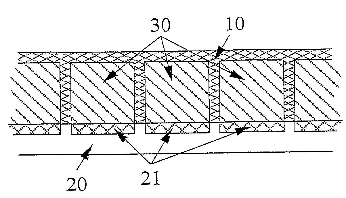
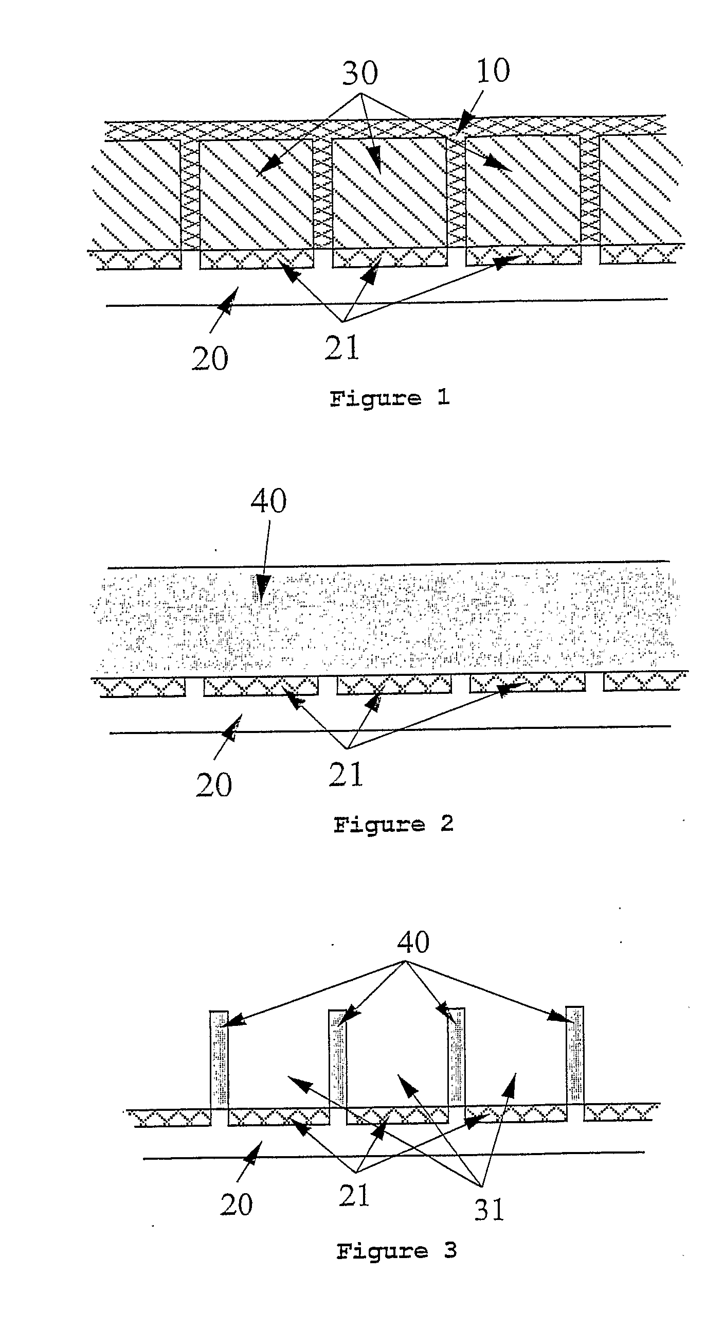
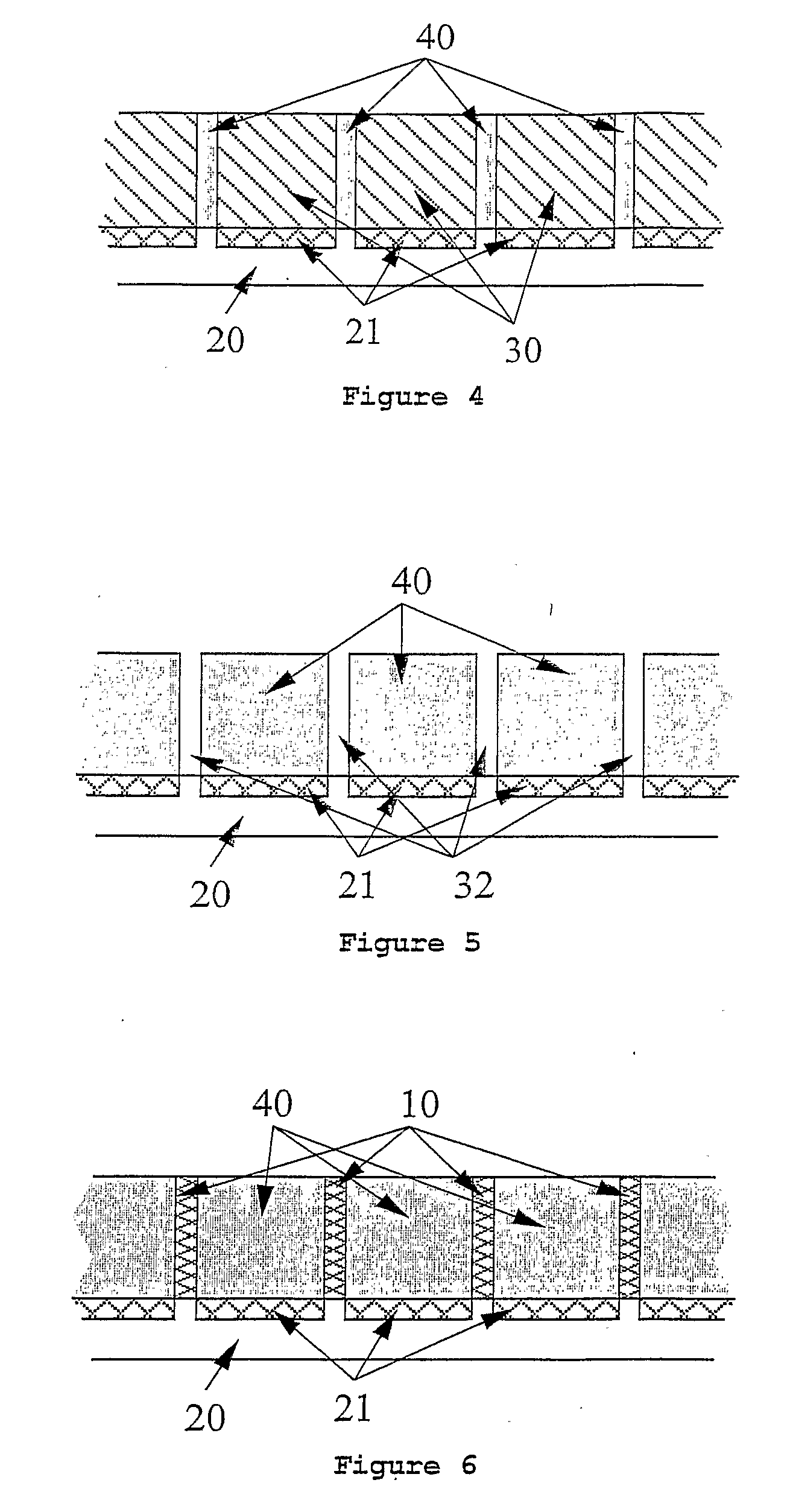
[0036]FIG. 1 shows a cross-sectional view of the x-ray detector matrix that consists in an image sensor (20), formed by a matrix of photodetectors (21), on which the matrix of scintillators (30), embedded in the reflectors (10), is placed. The radiation, coming from a radiation source placed above the detector, will penetrate in the reflector material (10) and reach the scintillators (30). The scintillators (30) will convert the radiation into visible light that is emitted in all directions. After a certain number of reflections, the visible light reaches the photodetectors (21), where it is detected.

[0037]The light guides prevent the dispersion of the visible light produced by the scintillators and the consequent interference between each pixel and its neighbors. It can be proved that the use of the light guides implies a much higher spatial resolution, as well as higher amplitude of the luminous signal that reaches the photodetector. As a higher amplitude of the luminous signal is...


PUM


Abstract

The present invention refers to a radiation or high energy particles detector, which can be used in obtaining digital radiographic images. The detector is composed of two parts: a scintillator matrix (30) embedded in walls manufactured from a reflector material (10), and a matrix of image elements (pixels), where each element is constituted by a photodetector (21) and an analog to digital converter. The walls manufactured from the reflector material (10) form light guides that prevent the dispersion of the visible light produced by the scintillators (30) and the consequent interference between each pixel and its neighbors.

Description

FIELD OF THE INVENTION[0001]The present invention belongs to the field of the detection of digital x-rays images, another type of radiation or high energy particles, particularly relevant in the medical areas and non destructive industrial tests. The present invention allows obtaining high quality and easy processing images, while reducing the amount of radiation necessary to obtain the images.BACKGROUND OF THE INVENTION[0002]When a radiation beam, for example in the x-ray spectrum, crosses a body, the photons that constitute the beam interact with the atoms of the body. As a result, the beam that leaves the body after crossing it has a defined pattern, where each area element has a density of photons that is different from its neighbors. These differences are caused due to more or less absorption of photons by the tissues that constitute the body. These different densities of x-ray photons can be translated by gray levels in an image, thus obtaining the radiography.[0003]In the fir...

Claims


Application Information

Patent Timeline
Patent Type & Authority Applications(United States)
IPC IPC(8): G01T1/20
CPCG01T1/2018H01L27/14625H04N5/32H01L27/14689H04N3/1568H01L27/14658H04N25/76G01T1/20183G01T1/20187G01T1/20184H04N25/65H04N25/30H04N25/77
Inventor VIEIRA DA ROCHA, JOSE GERARDOLANCEROS-MENDEZ, SENENTXU
Owner UNIVERSITY OF MINHO
Why Eureka
Eureka Blog
Learn More