Liquid crystal display apparatus, manufacturing method thereof, and liquid crystal projector

a technology of liquid crystal display and manufacturing method, which is applied in the direction of optics, instruments, non-linear optics, etc., can solve the problems of insufficient essential solution of technique, insufficient moisture resistance of resin structure, and considerable disadvantage, and achieves sufficient moisture resistance and large structure

Inactive Publication Date: 2009-06-11
CANON KK
View PDF20 Cites 35 Cited by
  • Summary
  • Abstract
  • Description
  • Claims
  • Application Information

AI Technical Summary

Benefits of technology

[0012]In cases where the technique described in Japanese Patent Application Laid-Open No. S60-026321 is used, the water permeability of the resin structure cannot ensure a sufficient moisture resistance. Therefore, the technique does not reach an essential solution, though bringing about a life prolonging effect under the high-temperature and high-humidity environment. When an attempt is made to obtain a sufficient moisture resistance by the provision of the resin structure, a portion of the resin structure which is formed at the peripheral portion of the liquid crystal display becomes thick and bulky, thus resulting in the entire liquid crystal display having a large structure. Such an arrangement is considerably disadvantageous to projection type image display apparatuses calling for downsizing in particular.

Problems solved by technology

S60-026321 is used, the water permeability of the resin structure cannot ensure a sufficient moisture resistance.
Therefore, the technique does not reach an essential solution, though bringing about a life prolonging effect under the high-temperature and high-humidity environment.
When an attempt is made to obtain a sufficient moisture resistance by the provision of the resin structure, a portion of the resin structure which is formed at the peripheral portion of the liquid crystal display becomes thick and bulky, thus resulting in the entire liquid crystal display having a large structure.
Such an arrangement is considerably disadvantageous to projection type image display apparatuses calling for downsizing in particular.
Further, the resin forming the adhesive may be thermally decomposed to produce impurities, which increase the likelihood of display deterioration due to image retention.
The projection type image display apparatuses, particularly the projection type image display apparatuses of the type using a reflection type liquid crystal display cannot obtain a good display quality because an uneven cell gap of the liquid crystal display is emphasized by a magnifying projection system.
Also, the display quality deterioration due to image retention caused by impurity ions is a more serious problem with the projection type image display apparatuses which apply intensive light to the respective liquid crystal displays over a prolonged time than with direct-view type liquid crystal display apparatuses.

Method used


Image

  • Liquid crystal display apparatus, manufacturing method thereof, and liquid crystal projector
  • Liquid crystal display apparatus, manufacturing method thereof, and liquid crystal projector
  • Liquid crystal display apparatus, manufacturing method thereof, and liquid crystal projector

Examples


exemplary embodiment 1

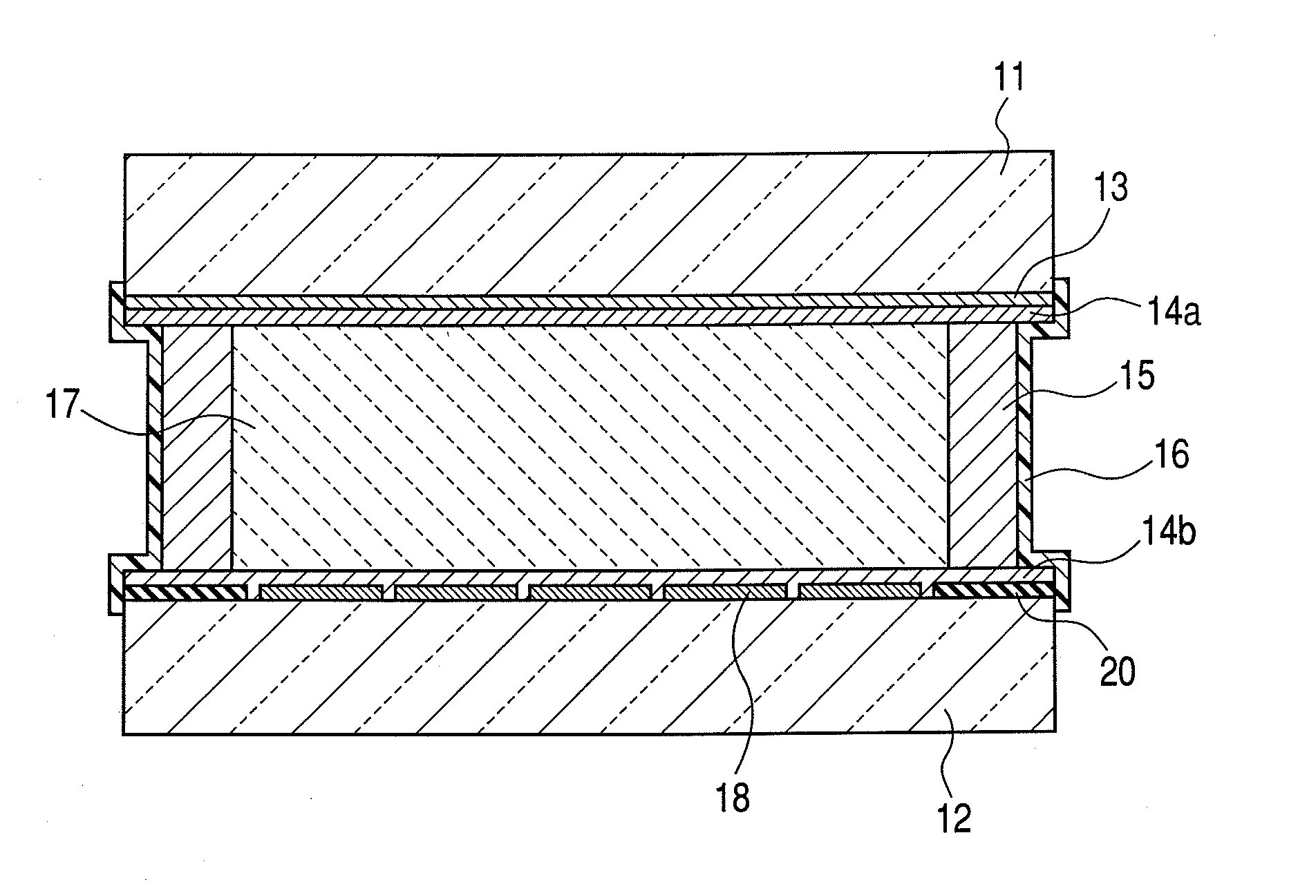
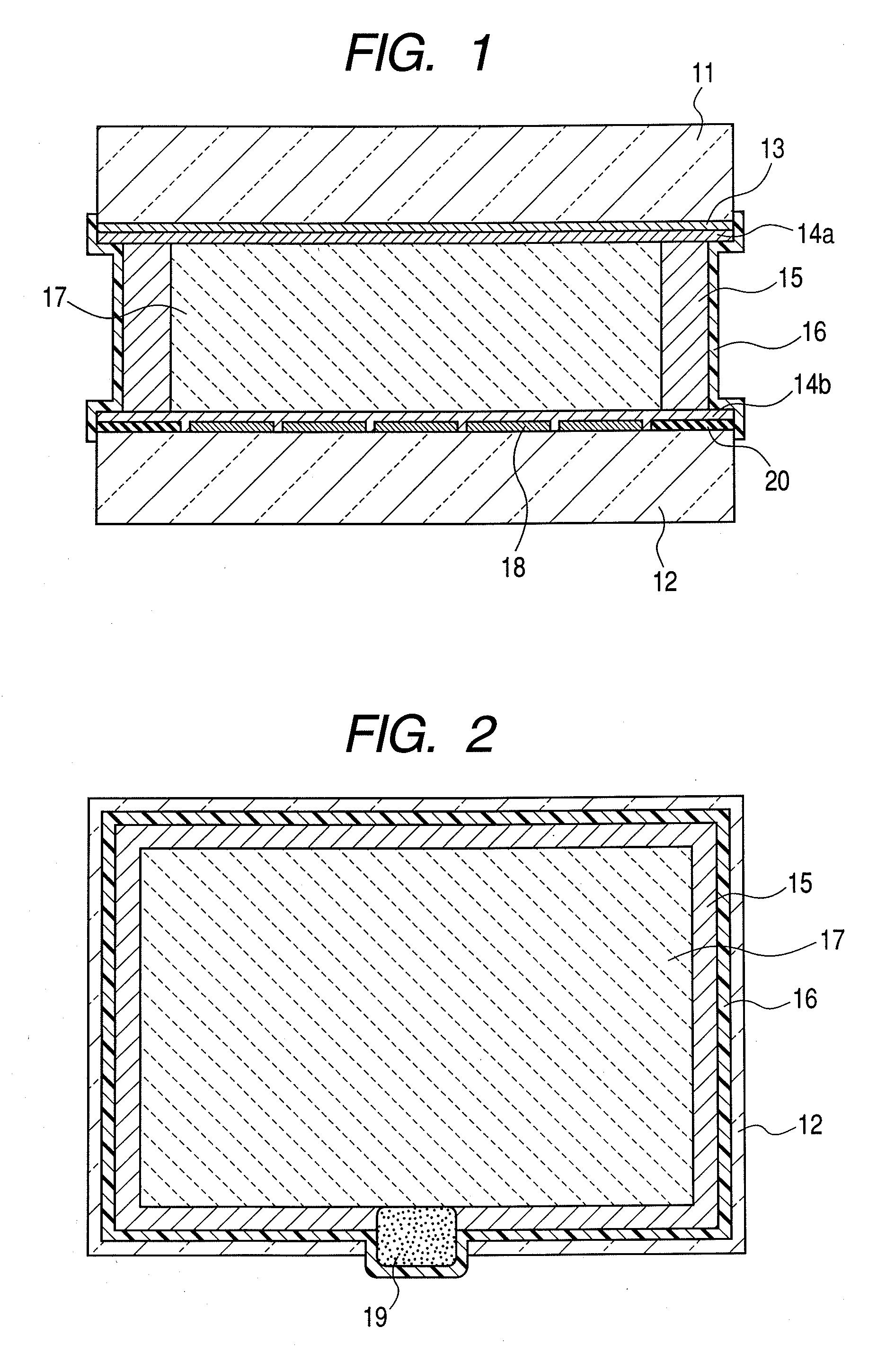
[0062]In exemplary embodiment 1, a liquid crystal display (i.e., liquid crystal display apparatus) was manufactured by performing the first and second steps of the above-described manufacturing method according to the present invention. Initially, the first step was performed to form the first structure (i.e., liquid crystal cell) as described above. In the first step, as described above, a process including forming the liquid crystal layer 17 by injecting the liquid crystal into the space defined by the pair of substrates 11 and 12 and the first sealing member 15, was performed.

[0063]Subsequently, the second step was performed to form the second structure (i.e., liquid crystal display) as described above. Specifically, TSF-458-100 (a product of GE Toshiba Silicones Co.) was used as the di-methyl-silicone oil serving as a main ingredient of the inorganic film 16. A thin coat of the di-methyl-silicone oil was applied to an outer periphery of the resin sealing adhesive used for periph...

exemplary embodiment 2

[0064]In exemplary embodiment 2, a liquid crystal display (i.e., liquid crystal display apparatus) was manufactured by performing the first and second steps as in exemplary embodiment 1. Initially, in the first step, the liquid crystal was injected into the space defined by the pair of substrates and the first sealing member to form the first structure, as in exemplary embodiment 1. In the second step, KF96-100cs (a product of Shin-Etsu Chemical Co., Ltd.) was used as the di-methyl-silicone oil serving as the main ingredient of the inorganic film 16, and a thin coat of the di-methyl-silicone oil was applied to an outer periphery of the resin sealing adhesive used in the peripheral sealing portion and the end-sealing portion.

[0065]Thereafter, an inorganic thin film was formed by irradiation with an ultraviolet irradiation at 5,000 mJ / cm2 in an ordinary temperature environment, to form the second structure. The display area was covered with an ultraviolet shielding mask in order to su...

exemplary embodiment 3

[0066]In exemplary embodiment 3, the third step of thermally treating the above-described first structure at a temperature lower than a phase transition temperature from a liquid crystal phase to a liquid phase of the liquid crystal, was inserted between the first and second steps. In the present embodiment, the thermal treatment was conducted at 80° C. for 240 hours.

[0067]Before providing the second sealing member 16 of high moisture durability, subjected to the thermal treatment are moisture and impurities present in the liquid crystal layer 17 and at the surfaces of the alignment films 14a and 14b as well as moisture and impurities of the first sealing member 15. The heating treatment turns the inside of the liquid crystal cell into a reduced moisture and impurity condition. Thereafter, the liquid crystal display was sealed with the second sealing member 16 having a high moisture resistance to enable the inside of the liquid crystal cell to keep the reduced moisture and impurity ...


PUM

PropertyMeasurementUnit
diameteraaaaaaaaaa
RHaaaaaaaaaa
temperatureaaaaaaaaaa

Abstract

A highly moisture-resistant liquid crystal display apparatus which is capable of suppressing display deterioration due to occurrence of image retention without impairing properties including gap controllability and alignment stability maintenance, and a manufacturing method thereof, are provided. The liquid crystal display apparatus includes: a first sealing member 15 arranged at an outer periphery of a liquid crystal layer 17 sandwiched between a pair of substrates 11 and 12; and a second sealing member 16 arranged at an outer periphery of the first sealing member 15 in contact with the pair of substrates 11 and 12. The second sealing member 16 is formed from an alkylsiloxane compound as a main ingredient which is formed into an inorganic film by irradiation with an ultraviolet radiation. The alkylsiloxane compound is a di-alkylsiloxane compound or di-methyl-siloxane compound.

Description

BACKGROUND OF THE INVENTION[0001]1. Field of the Invention[0002]The present invention relates to a liquid crystal display apparatus, a manufacturing method thereof, and a liquid crystal projector using the liquid crystal display apparatus.[0003]2. Description of the Related Art[0004]In recent years, projection type image display apparatuses of the type using a reflection type liquid crystal display called “LCOS (Liquid Crystal on Silicon) display” in the art of liquid crystal displays have been widespread. Such a projection type image display apparatus is capable of displaying images that are smoother and have higher-definition and higher color reproducibility than projection type image display apparatuses of the type using a transmission type liquid crystal display.[0005]Such liquid crystal displays as reflection type liquid crystal displays of the LCOS type, in general, have a structure in which a liquid crystal member is held by peripheral sealing formed at a peripheral portion o...

Claims


Application Information

Patent Timeline
Patent Type & Authority Applications(United States)
IPC IPC(8): G02F1/1339
CPCG02F1/1339G02F2202/023G02F2001/133311G02F1/136277G02F1/133311
Inventor MIZUNO, HIROSHISAKAGUCHI, KIYOFUMI
Owner CANON KK
Why Eureka
Try Eureka