

Radiographing apparatus and image processing program
a technology of radiation processing and imaging apparatus, applied in the field of radiation processing apparatus and image processing program, can solve the problems of limited correction accuracy of beam hardening effect, limited application range, and difficult to use it widely in clinical practice, and achieve excellent contrast and high detail
- Summary
- Abstract
- Description
- Claims
- Application Information
AI Technical Summary
Benefits of technology
Problems solved by technology
Method used
Image

Examples
embodiment 1
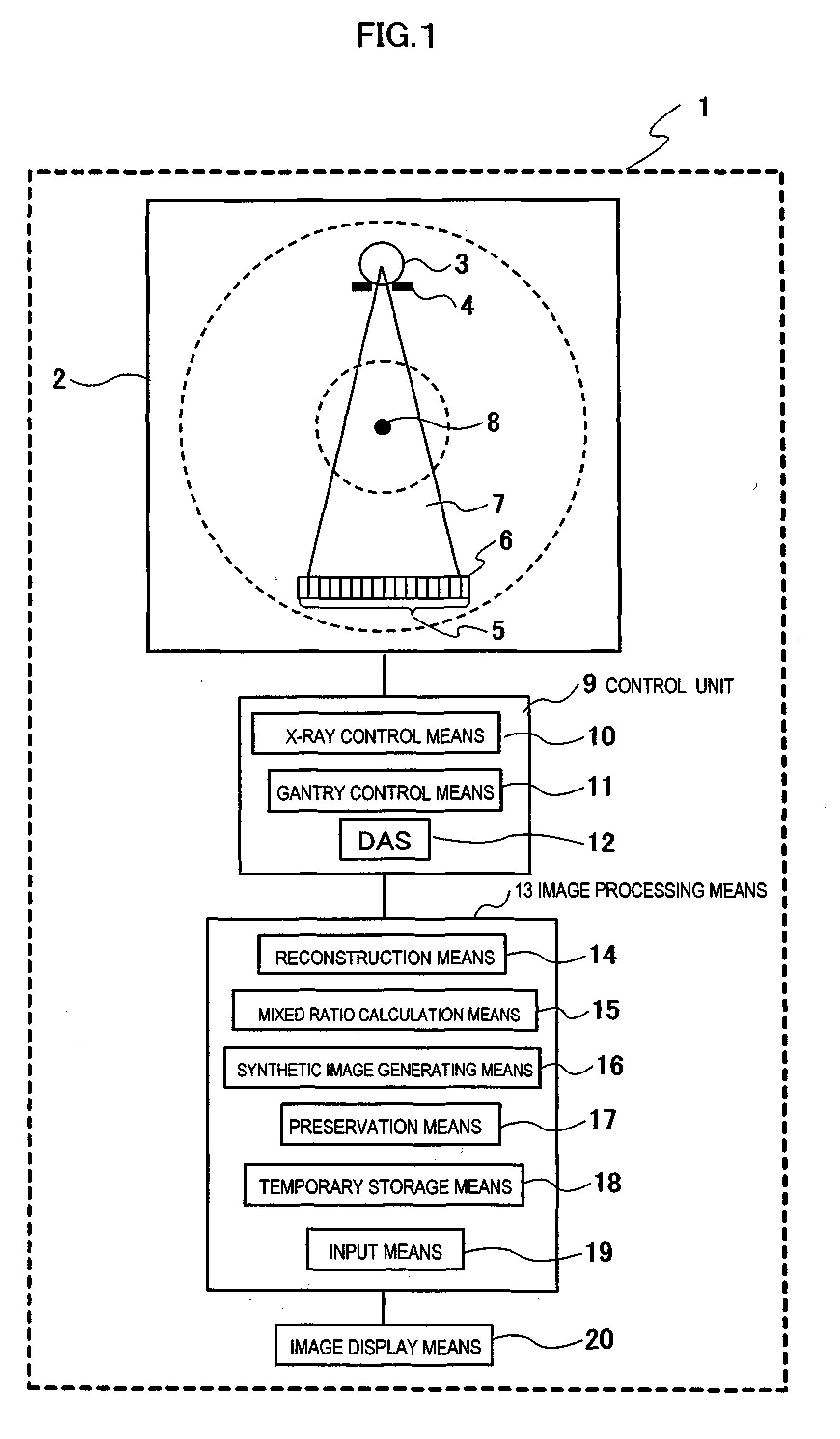
[0115]FIG. 1 is a diagram illustrating a preferable embodiment of a radiographing apparatus (hereafter, this is abbreviated as an “X-ray CT scanner”) which relates to the present invention. An X-ray CT scanner 1 which relates to the present invention includes a gantry 2, and the gantry 2 has an X-ray source 3, a collimator 4, and a detector array 5 which are located on counter faces of the gantry 2. The detector array 5 is formed of detector elements 6 which detect X-rays which transmit an object to be examined on a bed which is not illustrated. The detector elements 6 are arranged in a form of a transverse row, or a form of a plurality of parallel transverse rows. Each of the detector elements 6 generates an electric signal expressing strength of an incident X-ray beam, in other words, attenuation at the time of the X-ray beam transmitting an object to be examined. X-ray projection data is acquired by the gantry 2 rotating with centering on a rotation center 8 in a state that an X-...
embodiment 2
[0130]FIG. 5 is a process flow from projection data acquisition to synthetic image display in the second embodiment of the X-ray CT scanner which relates to the present invention.
[0131]At step S501 projection data is acquired first (S501). A method of data acquisition may be the same as that of the first embodiment.
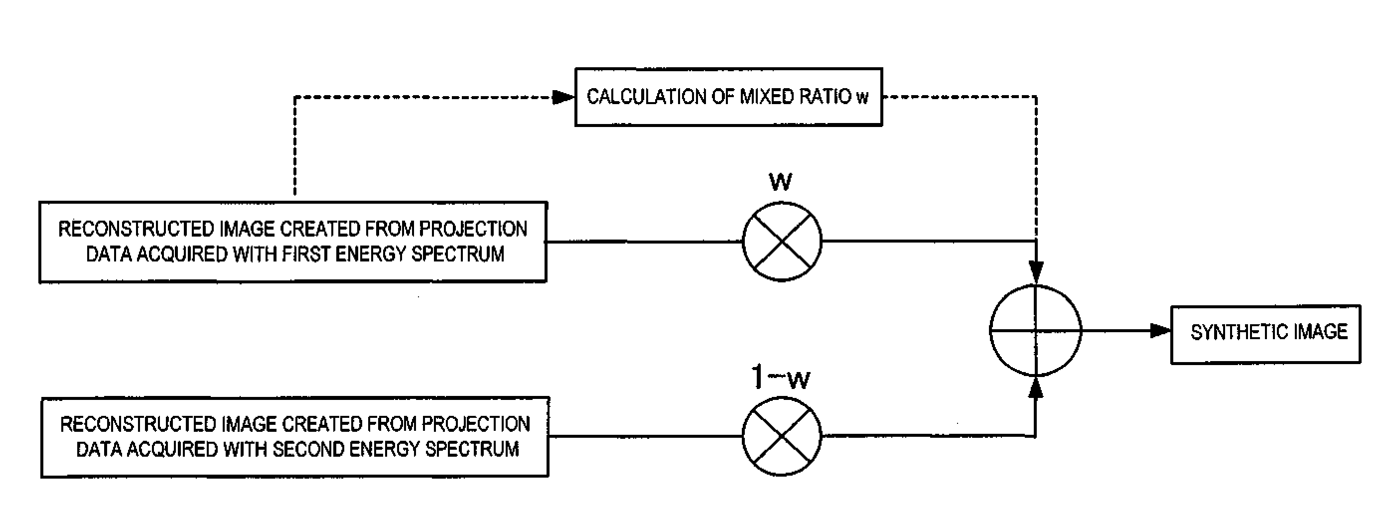
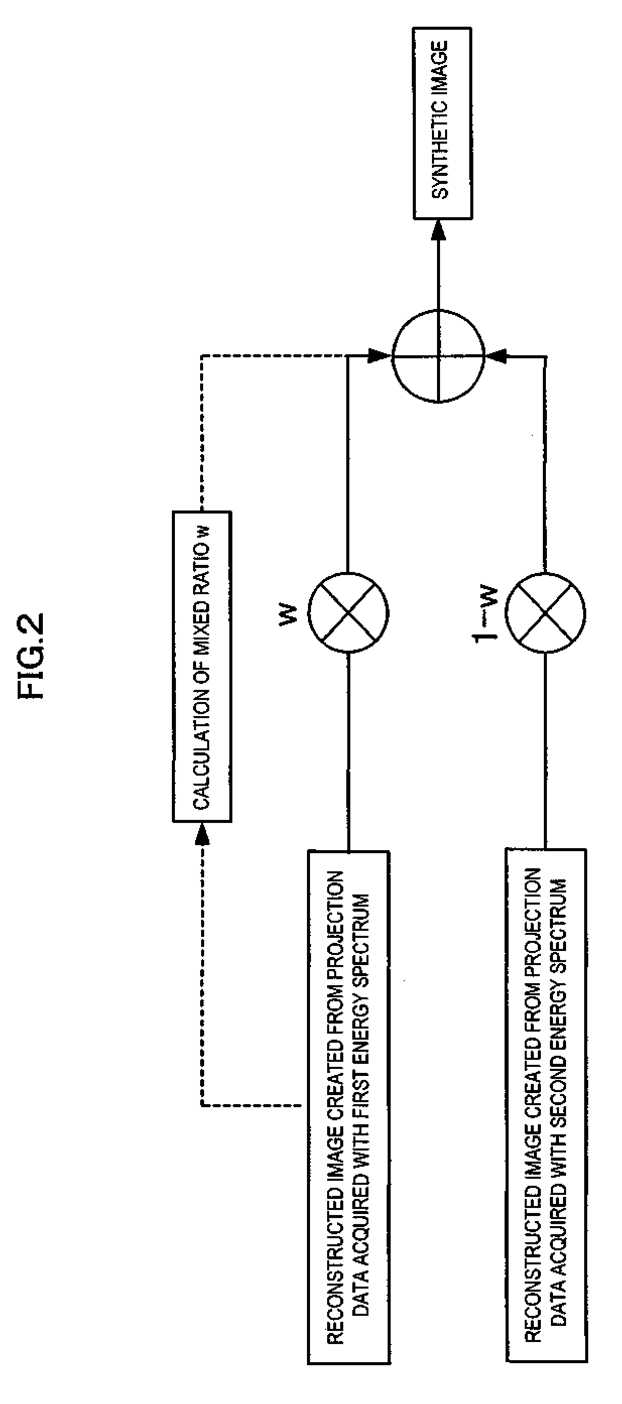
[0132]At step S502, the reconstruction means 14 generates the first reconstructed image and the second reconstructed image about projection data in the respective energy spectra (S502).
[0133]At step S503, the mixed ratio calculation means 15 calculates an effectual atomic number in a noticed picture element or a local area (S503). The mixed ratio calculation means 15 segments the first reconstructed image and the second reconstructed image every tissue which has the same vital function (segmentation). Instead of obtaining a whole damping coefficient such as a conventional type CT, a multi-energy CT can obtain a pair of images which express different attenuations from Comp...
embodiment 3
[0141]FIG. 7 is a process flow from projection data acquisition to synthetic image display in a third embodiment of the X-ray CT scanner which relates to the present invention.
[0142]At step S701, projection data is acquired first (S701). A method of data acquisition may be the same as those of the first embodiment and the second embodiment.
[0143]At step S702, the reconstruction means 14 generates the first reconstructed image and the second reconstructed image about projection data in the respective energy spectra (S702).
[0144]At step S703, the mixed ratio calculation means 15 finds for a local standard deviation of pixel values around a noticed picture element, or a local standard deviation in a local area (S703).
[0145]At step S704, the mixed ratio calculation means 15 compares a local standard deviation (SD1) in the first reconstructed image generated from the projection data acquired in the first energy spectrum with a local standard deviation (SD2) in the second reconstructed im...
PUM
 Abstract
Description
Claims
Application Information