Roots type gear compressor with helical lobes having feedback cavity

a gear compressor and feedback cavity technology, applied in the direction of machines/engines, rotary/oscillating piston pump components, liquid fuel engines, etc., can solve the problems of affecting the rotation speed of the rotor

Inactive Publication Date: 2009-06-11
592301 ALBERTA +1
View PDF12 Cites 8 Cited by
  • Summary
  • Abstract
  • Description
  • Claims
  • Application Information

AI Technical Summary

Benefits of technology

[0030]While not necessary to the operation of the compressor/supercharger of the present invention, it is contemplated in a preferred embodiment that an aperture area be provided on a lower point of intersection of said mutually adjacent chambers, proximate said rear end of said gear compressor/supercharger, which aperture is in fluid communication with the plenum or chamber. Such aperture assists in allo...

Problems solved by technology

In early non-helix type gear compressors having lobed rotors, it was realized that at high circumferential velocities of the gear rotors in the range of 1/10 the speed of sound, adverse momentum loses become significant.
These losses occur as a result of the sudden exposure of the gear wells between the gear lobes which are filled with low pressure inlet gas to the high pressure outlet region, bringing about a violent rush of high pressure gas back against the oncoming gear lobe thereby creating adverse momentum forces which impede the rotor's rotation and thereby require greater hor...

Method used


Image

  • Roots type gear compressor with helical lobes having feedback cavity
  • Roots type gear compressor with helical lobes having feedback cavity
  • Roots type gear compressor with helical lobes having feedback cavity

Examples


example 1

[0057]In order to evaluate efficiency increases to gear compressors and supercharger arising from the inventive modifications herein described and claimed, a standard prior art supercharger was tested to provide a base comparison.

[0058]Accordingly, for this purpose a publicly available model 14 / 71 standard helix supercharger manufactured by Kobelco Compressors (America) Inc. of Elkhart, Ind., exclusively distributed by DPME Inc. of Stevensville Mich., part number KS14S2LS, having a pair of helical 3-lobe rotors, each with a standard (but opposite) 60° helix angle per 15 inch rotor length, was used.

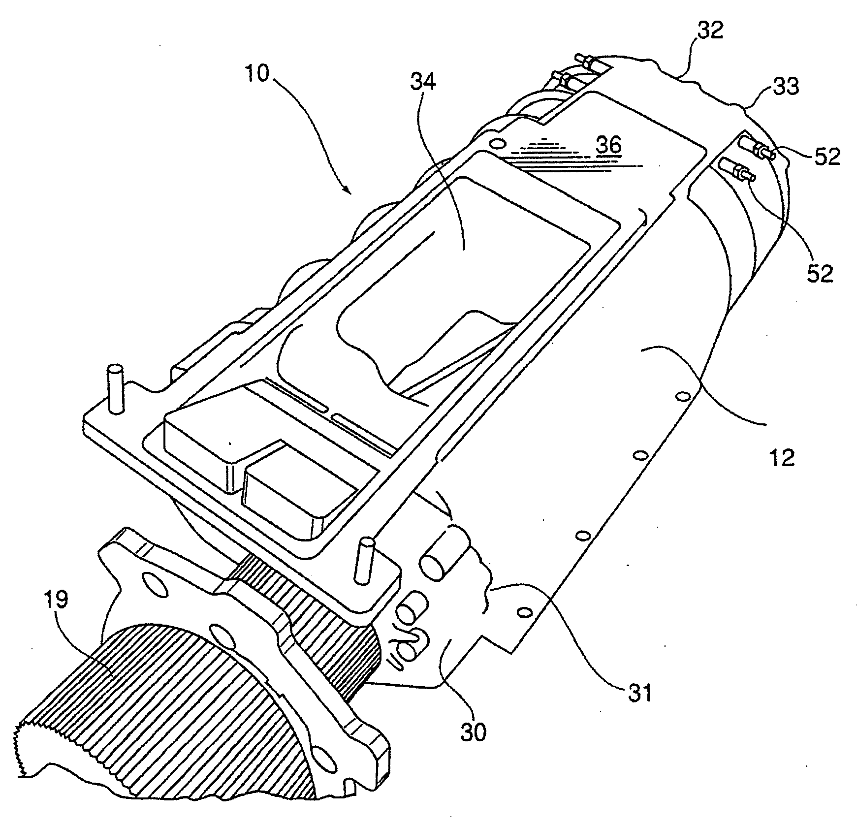
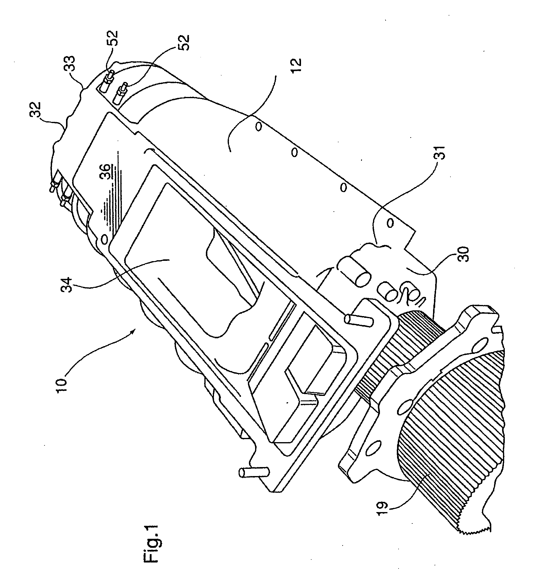
[0059]Such standard model 14 / 71 supercharger was inter alia modified to mill an aperture area 95 on a lower point of intersection 96 of mutually adjacent rotor chambers 14a, 14b thereof proximate the rear end 32 of the supercharger 10, commencing at about 1.5 inches from a rear wall thereof, to a maximum depth proximate the rear end of approximate 0.75 inches. Such supercharger via a g...

example 2

[0062]Above model 14 / 71 Kobelco supercharger was modified to replace stock rear cover (end wall) with a rear end wall 33 having a cavity / plenum 60 of the present invention, of relative dimensions as shown in drawings FIG. 6 hereto.

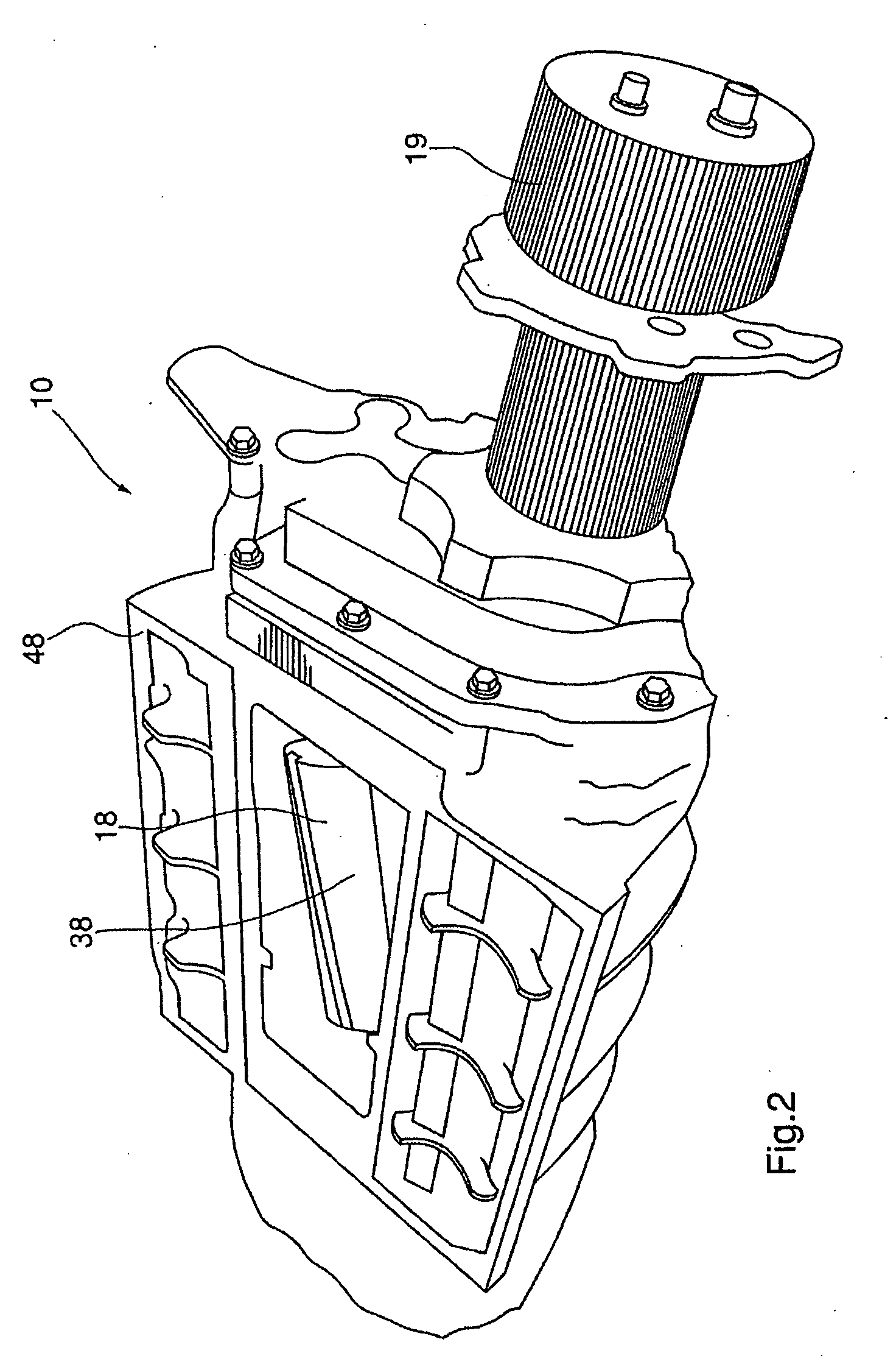
[0063]In particular, the cavity / plenum 60 in modified rear end wall member 33 was situated below the axis of rotation 20 of each of rotors 16a, 16b, and was of a length slightly greater than the distance between the respective axis of rotation 20 of each of said rotors 16a, 16b, as seen from FIG. 6 hereto. For the purpose of this test run, as regards the lower aperture 75 in rear end wall member 33, such was for this test run “blocked off” by affixing a blanking plate, so as to prevent fluid communication with air discharged from the high pressure discharge port 38 of the supercharger 10. The volumetric size of cavity / plenum 60 utilized in rear end wall 33 of FIG. 6 with lower aperture 75 blanked off was approximately 8.6 cubic inches.

[0064]The ide...

example 3

[0065]Above model 14 / 71 Kobelco supercharger was further modified to replace the modified end wall as shown in FIG. 6 with a further modified rear end wall, as shown in FIGS. 8 & 9, having a cavity / plenum 60 of relative dimensions as shown in FIGS. 8 & 9 hereto.

[0066]Again, the cavity / plenum 60 in modified rear end wall member 33 was situated below the axis of rotation 20 of each of rotors 16a, 16b, and was of a length slightly greater than the distance between the respective axis of rotation 20 of each of said rotors 16a, 16b, as seen from FIG. 9 hereto. Again, for the purpose of this test run, as regards the lower aperture 75 in rear end wall member 33, such was for this test run “blocked off” by affixing a blanking plate, so as to prevent fluid communication with air discharged from the high pressure discharge port 38 of the supercharger 10. The volumetric size of cavity / plenum 60 utilized in rear end wall 33 of FIG. 9 with lower aperture 75 blanked off was approximately ...


PUM


Abstract

A gear compressor or supercharger for compressing compressible fluids such as air, having a pair of intermeshing helical lobed rotors. A plenum or cavity is provided at a rear end of the gear compressor, situated rearwardly of said rotors and below an respective axis of rotation of each of said rotors, which spans at least a distance between said respective longitudinal axis of rotation of each of said rotors. In a preferred embodiment the plenum is in direct fluid communication with high pressure fluid which is discharged from said high pressure discharge port. The above modification improves the efficiency of the compressor, particularly at high revolutions.

Description

FIELD OF THE INVENTION[0001]This invention relates to Roots-type gear compressors or blowers, and in one aspect thereof relates to a modified supercharger for an internal combustion engine.BACKGROUND OF THE INVENTION AND DESCRIPTION OF THE PRIOR ART[0002]Roots-type gear compressors are well known in the prior art, and have existed in various configurations for many years.[0003]Such Roots style gear compressors typically comprise a pair of intermeshing rotors placed side by each so as to permit meshing of lobes on each of said rotors, for the purpose of transferring quantities of compressible fluid from a low pressure region to a high pressure region.[0004]In early non-helix type gear compressors having lobed rotors, it was realized that at high circumferential velocities of the gear rotors in the range of 1 / 10 the speed of sound, adverse momentum loses become significant. These losses occur as a result of the sudden exposure of the gear wells between the gear lobes which are filled ...

Claims


Application Information

Patent Timeline
IPC IPC(8): F01C1/16
CPCF04C15/062F04C2240/30F04C18/126
Inventor KAPLAN, JIRKADAVENPORT, LES
Owner 592301 ALBERTA
Why Eureka
Try Eureka