

Control Apparatus for Spark-Ignition Engine
- Summary
- Abstract
- Description
- Claims
- Application Information
AI Technical Summary
Benefits of technology
Problems solved by technology
Method used
Image

Examples
first embodiment
[0049]The configuration of a control apparatus for a spark-ignition engine according to the present invention, and the operation thereof, will be described below with reference to FIGS. 1 through 7.
[0050]First of all, the configuration of a system in which the control apparatus for the spark-ignition engine according to this embodiment is applied to an automobile gasoline engine will be described with reference to FIG. 1.
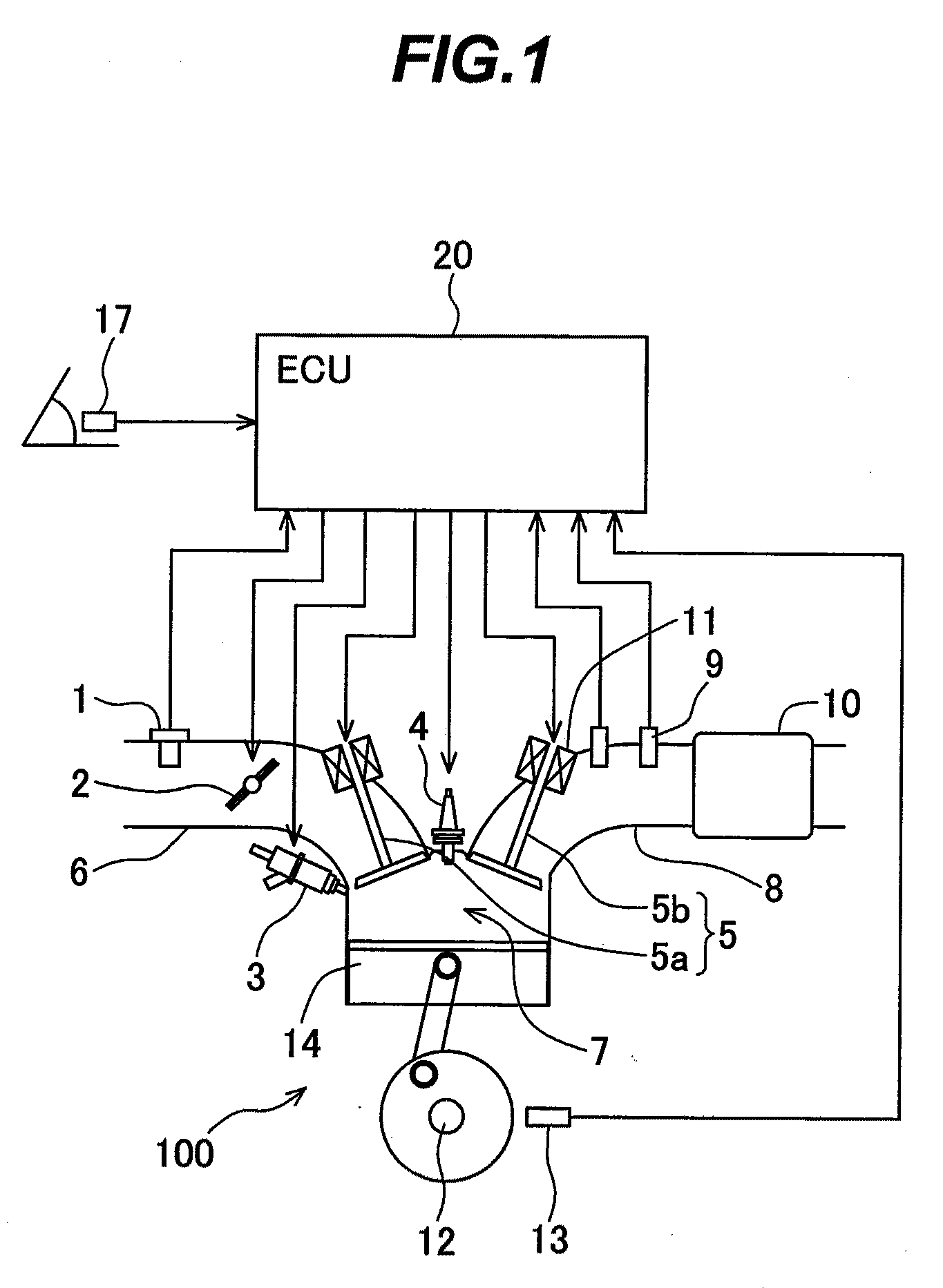
[0051]FIG. 1 is a diagram illustrating the configuration of the system in which the control apparatus for the spark-ignition engine according to the first embodiment of the present invention is applied to the automobile gasoline engine.
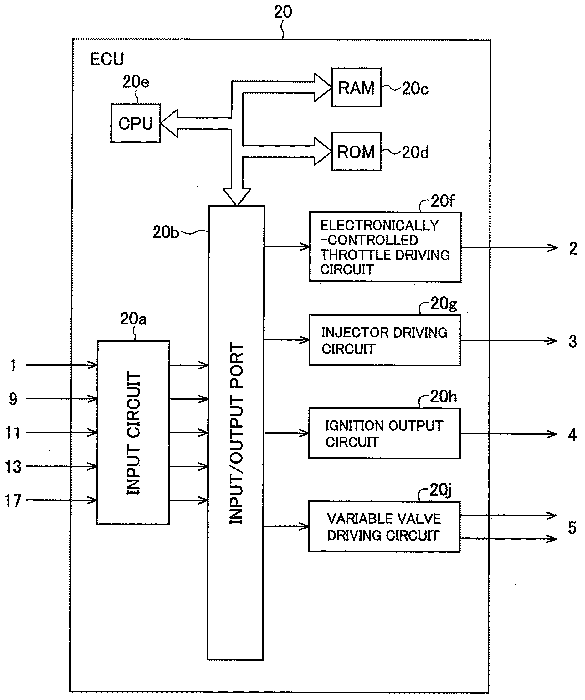
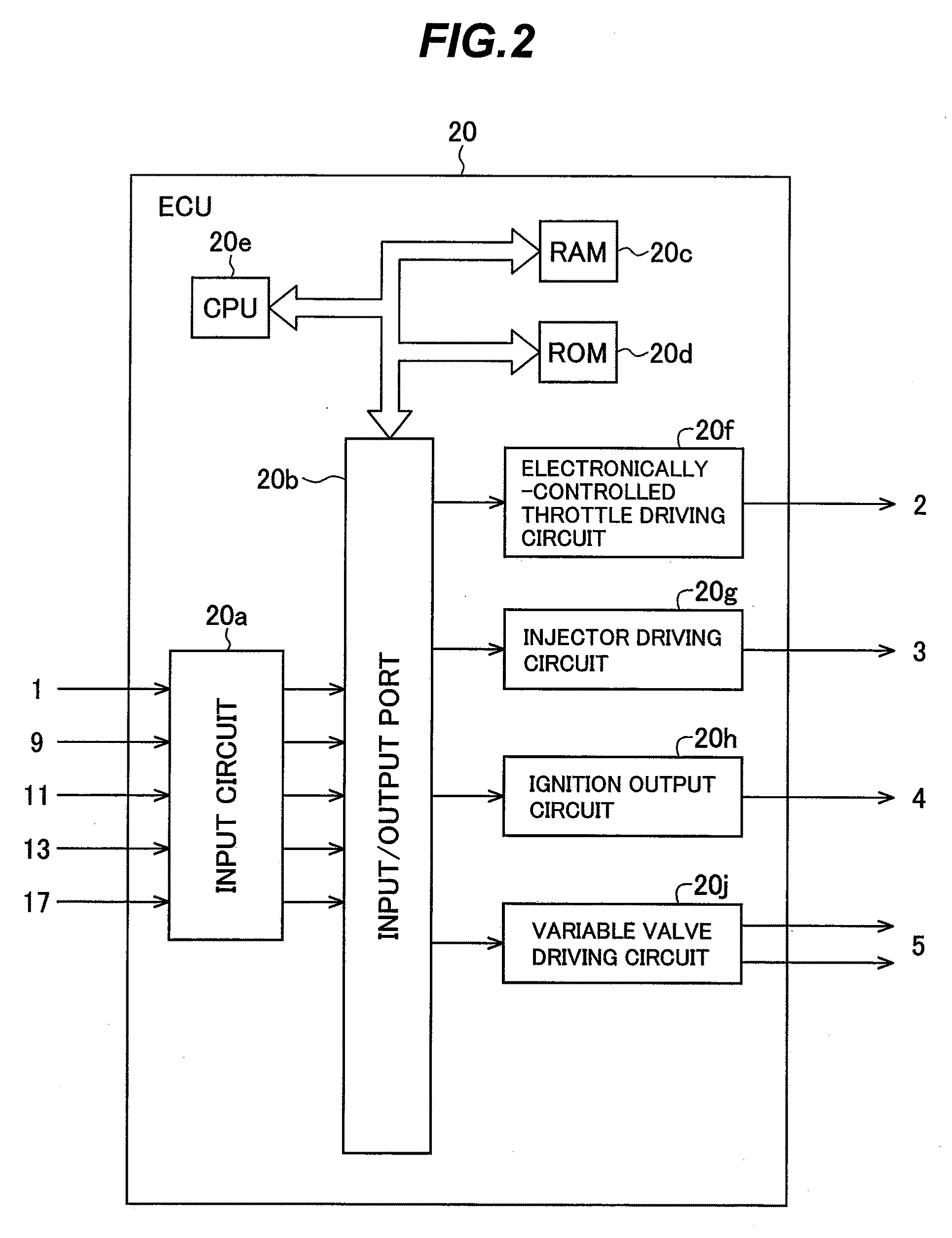
[0052]An engine 100 is an automobile gasoline engine that performs spark-ignition combustion. The engine 100 includes an intake pipe 6 having an airflow sensor 1 for measuring the amount of intake air and an electronic control throttle 2 for adjusting an intake flow rate. Each of the airflow sensor 1 and the electronic control throttl...
second embodiment
[0094]Next, the configuration of a control apparatus for a spark-ignition engine according to the present invention, and the operation thereof, will be described with reference to FIGS. 8, 9. The configuration of a system in which the control apparatus for the spark-ignition engine according to this embodiment is applied to an automobile gasoline engine is similar to that shown in FIG. 1. The control apparatus for the spark-ignition engine according to this embodiment is configured in a manner similar to that shown in FIG. 2. A high-load operation area used by the control apparatus for the spark-ignition engine according to this embodiment is similar to that shown in FIG. 3. Fuel injection control performed by the control apparatus for the spark-ignition engine according to this embodiment is similar to that shown in FIG. 4.
[0095]FIGS. 8A through 8C are timing charts each illustrating the fuel injection control for the high-load operation area performed by the control apparatus for ...
third embodiment
[0107]Next, the configuration of a control apparatus for a spark-ignition engine according to the present invention, and the operation thereof, will be described with reference to FIGS. 10 through 12. The configuration of a system in which the control apparatus for the spark-ignition engine according to this embodiment is applied to an automobile gasoline engine is similar to that shown in FIG. 1. The control apparatus for the spark-ignition engine according to this embodiment is configured in a manner similar to that shown in FIG. 2. A high-load operation area used by the control apparatus for the spark-ignition engine according to this embodiment is similar to that shown in FIG. 3.
[0108]FIG. 10 is a flowchart illustrating how the fuel injection is controlled by the control apparatus for the spark-ignition engine according to the third embodiment of the present invention. FIGS. 11A through 11C are timing charts each illustrating the fuel injection control for the high-load operatio...
PUM
 Abstract
Description
Claims
Application Information