Dedicated heat recovery chiller

a heat recovery chiller and dedicated technology, applied in the operation mode of machines, refrigeration components, light and heating apparatus, etc., can solve the problem of differential pressure change between supply and return manifolds, and achieve the effect of reducing system load, reducing power requirements for the pump, and reducing system load

Inactive Publication Date: 2009-06-18
MULTISTACK
View PDF2 Cites 38 Cited by
  • Summary
  • Abstract
  • Description
  • Claims
  • Application Information

AI Technical Summary

Benefits of technology

[0018]By using a variable speed or variable capacity pump, the power requirements for the pump is able to be reduced during reduced system load. Thus, as the load decreases and modular units are made inactive, the valve on those inactive units is selectively closed to thereby close the heat exchangers thereof to the heat exchange fluid. The power supplied to the pump is then also reduced due to the reduced pumping load resulting from a reduced number of heat exchangers in the circuit.

Problems solved by technology

This causes a change in the differential pressure between the supply and return manifolds.

Method used


Image

  • Dedicated heat recovery chiller
  • Dedicated heat recovery chiller
  • Dedicated heat recovery chiller

Examples


example 1

Heating Mode

HUSP=125° F.

HLSP=115° F.

VSP=50%

[0091]The Heating No Load Point (HNLP) is then calculated as follows:

HNLP=HUSP−(VSP*(HUSP−HLSP)=125° F.−(50%*(125° F.−115° F.)=120° F.

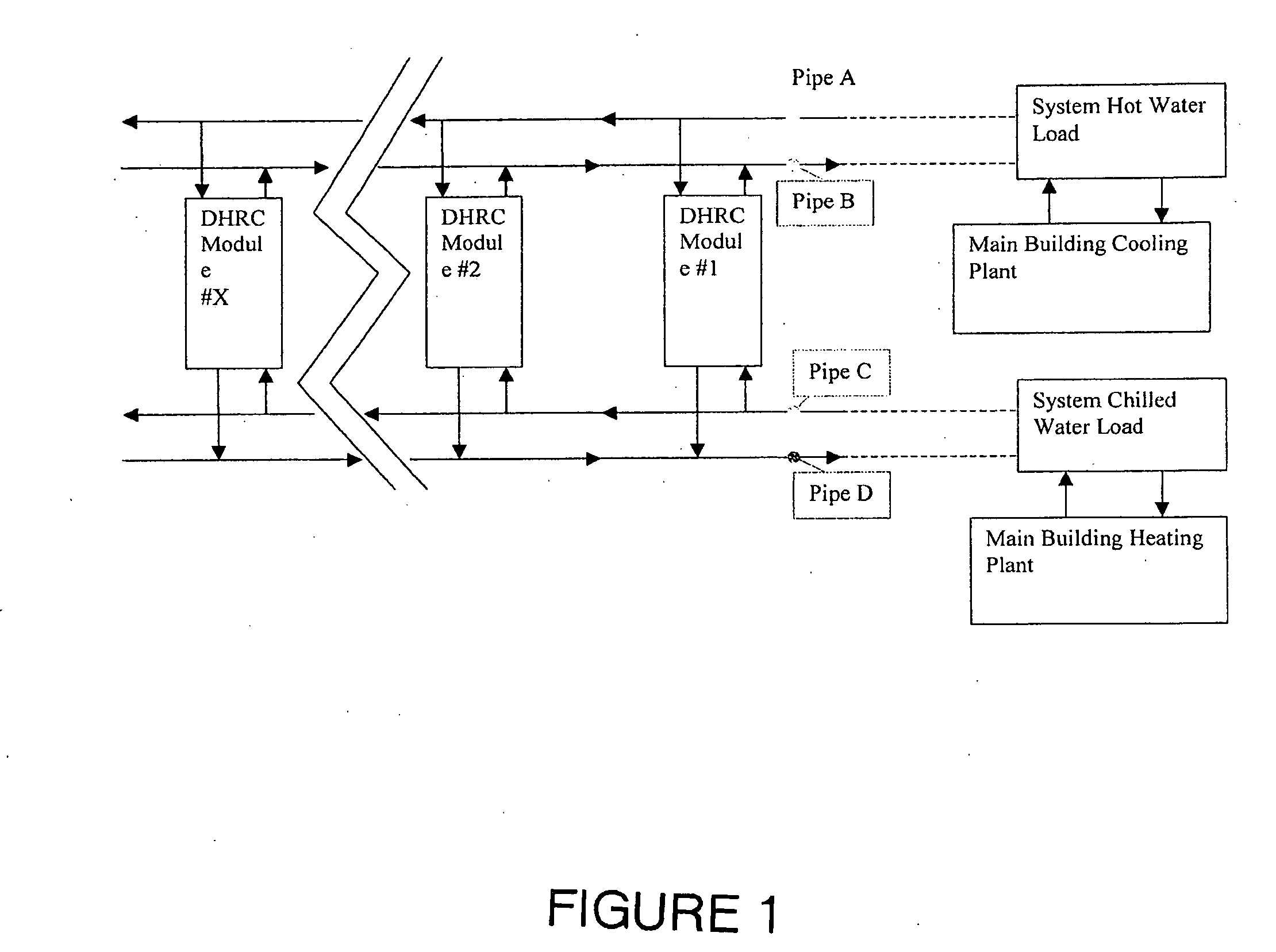
[0092]Therefore, in this case, the DHRC will operate its capacity controls based on temperature in Pipe A as it moves between the HLSP and the HNLP. That is, it will operate its capacity controls between measured temperatures of 115° F. and 120° F. in Pipe A. Any time the temperature in Pipe A is at or below the HLSP (115° F.), the DHRC will operate at 100% capacity. Any time the temperature in Pipe A at or above the HNLP (120° F. in this case), the DHRC will operate at 0% capacity. In between these two temperatures in Pipe A, there will be a linear relationship between capacity and temperature based on the DHRC's ability to step down. That is, if the DHRC has five-steps of capacity control (0%, 20%, 40%, 60%, 80%, and 100%). Then the following control logic will dictate DHRC loading:

Whenever the temperature ...

example 2

Cooling Mode


PUM


Abstract

A heating and/or cooling system which incorporates one or more modular dedicated heat recovery refrigeration units each of which includes at least one compressor, an evaporator and a condenser. The system captures and utilizes condenser circuit heat which would otherwise be wasted. A variable speed circulating water pump circulates water through each evaporator/condenser, which are connected in parallel across the respective supply line and return line. A master controller activates and deactivates individual compressors in accordance with load demand. Shut-off valves close off the water flow through the respective evaporator and/or condenser of any units deactivated and the resulting changes in the pressure differential in the supply and return lines is sensed by sensor which sends a signal to the pump motor speed controller which changes the output of the pump to restore a predetermined pressure differential.

Description

BACKGROUND OF THE INVENTION[0001]1. Field of the Invention[0002]This invention relates to improvements in heating and cooling systems and relates particularly to improvements in air conditioning and chilling systems. Particularly, the invention relates to a dedicated heat recovery chiller and control systems for such a chiller.[0003]The dedicated heat recovery chiller and control system of the present invention utilizes heat otherwise rejected and wasted from a condenser circuit of a refrigeration system to offset heating load which would otherwise need to be provided from a heating source. This system raises the overall thermal efficiency of a building system, reduces energy consumption overall, and saves energy costs.[0004]Recent developments in air conditioning systems involve the utilization of modular refrigeration units each having an evaporator and condenser in heat exchange relation with the fluid to be cooled and / or heated. With the modular system, each refrigeration unit i...

Claims


Application Information

Patent Timeline
Patent Type & Authority Applications(United States)
IPC IPC(8): F25B1/00
CPCF25B29/003Y02B30/745F25B2600/13F25B2400/06Y02B30/70
Inventor PLATT, MARKKINCAID, BENNY L.
Owner MULTISTACK
Why Eureka
Try Eureka