
Localized heating of edge seals for a vacuum insulating glass unit, and/or unitized oven for accomplishing the same

a vacuum insulating glass and unit heating technology, applied in the field of edge sealing techniques for vacuum insulating glass (vig) units, can solve the problems of undesirable high temperature and long heating time of the entire assembly utilized in the formulation of edge sealing b>4, >, and adversely affect certain low-e coating(s), so as to increase the likelihood of glass deformation and/or breakage

Active Publication Date: 2009-06-18
GUARDIAN GLASS LLC
View PDF25 Cites 85 Cited by
  • Summary
  • Abstract
  • Description
  • Claims
  • Application Information

AI Technical Summary

Benefits of technology

[0011]Even when non-tempered glass substrates are used, the high temperatures applied to the entire VIG assembly may melt the glass or introduce stresses. These stresses may increase the likelihood of deformation of the glass and / or breakage.
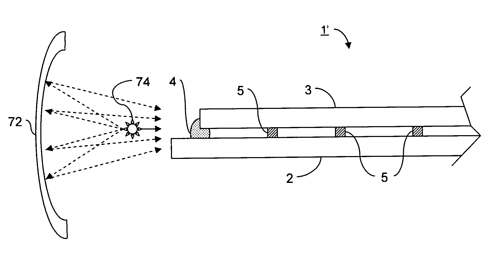
[0013]An aspect of certain example embodiments of this invention relates to applying localized heating to the periphery of a unit to form edge seals to reduce the heating of the non-peripheral areas of the unit and thereby reduce the chances of the substrates breaking.
[0017]Another aspect of certain example embodiments relates to reducing the amount of post-tempering heating time necessary to form a peripheral / edge seal in a vacuum IG unit.

Problems solved by technology

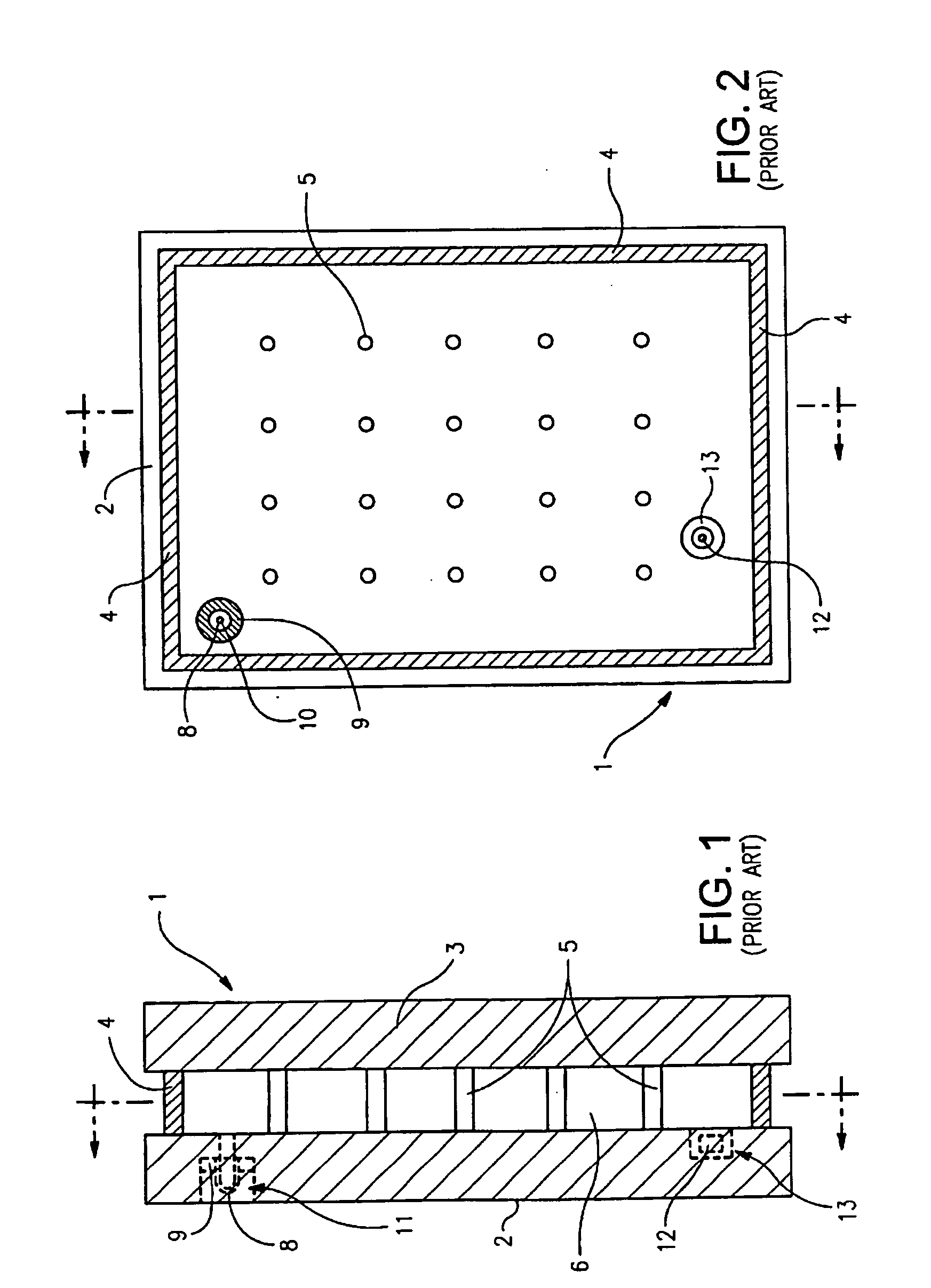
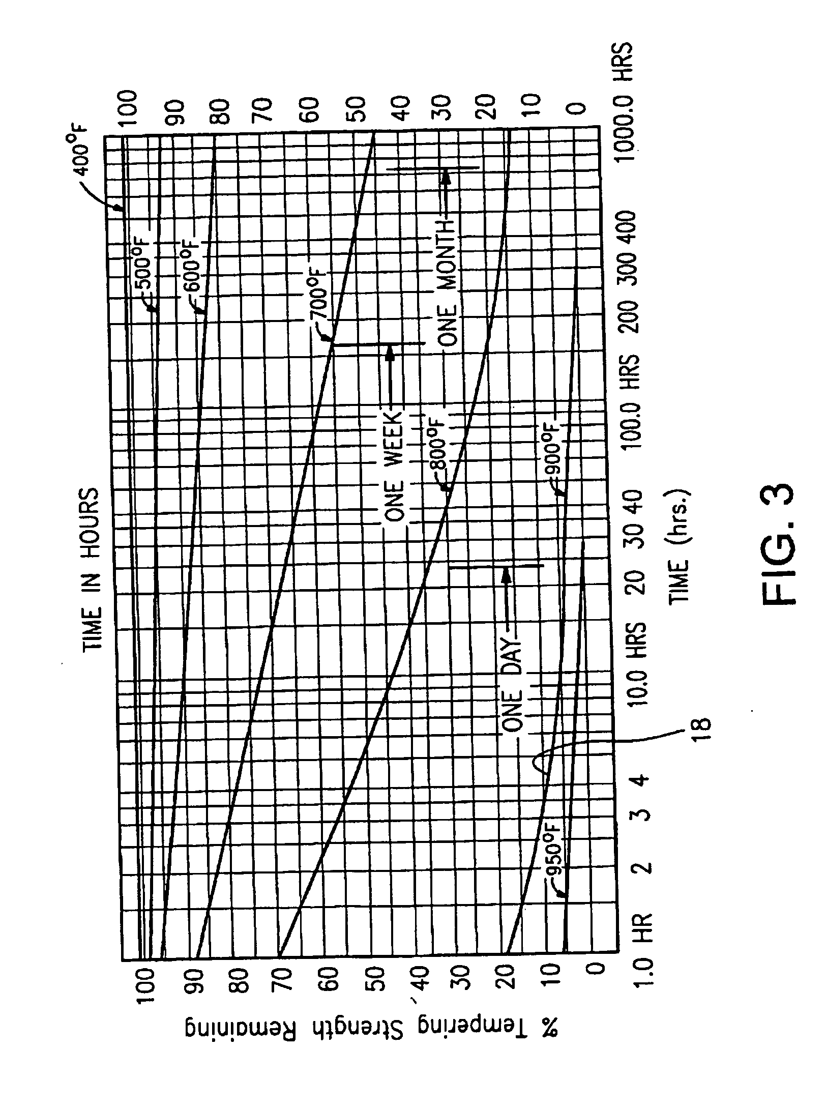
Unfortunately, the aforesaid high temperatures and long heating times of the entire assembly utilized in the formulation of edge seal 4 are undesirable, especially when it is desired to use a heat strengthened or tempered glass substrate(s) 2, 3 in the vacuum IG unit.
Moreover, such high processing temperatures may adversely affect certain low-E coating(s) that may be applied to one or both of the glass substrates in certain instances.
Such a significant loss (i.e., 80% loss) of temper strength is of course undesirable.
This may or may not be desirable in some instances.
Even when non-tempered glass substrates are used, the high temperatures applied to the entire VIG assembly may melt the glass or introduce stresses.
These stresses may increase the likelihood of deformation of the glass and / or breakage.

Method used


Image

  • Localized heating of edge seals for a vacuum insulating glass unit, and/or unitized oven for accomplishing the same
  • Localized heating of edge seals for a vacuum insulating glass unit, and/or unitized oven for accomplishing the same
  • Localized heating of edge seals for a vacuum insulating glass unit, and/or unitized oven for accomplishing the same

Examples


Embodiment Construction

[0032]Certain embodiments of this invention relate to an improved peripheral or edge seal in a vacuum IG window unit, and / or a method of making the same. “Peripheral” and “edge” seals herein do not mean that the seals are located at the absolute periphery or edge of the unit, but instead mean that the seal is at least partially located at or near (e.g., within about two inches) an edge of at least one substrate of the unit. Likewise, “edge” as used herein is not limited to the absolute edge of a glass substrate but also may include an area at or near (e.g., within about two inches) of an absolute edge of the substrate(s). Also, it will be appreciated that as used herein the term “VIG assembly” refers to an intermediate product prior to the VIG's edges being sealed and evacuation of the recess including, for example, two parallel-spaced apart substrates and a flit. Also, while the flit may be said to be “on” or “supported” by one or more of the substrates herein, this does not mean t...


PUM

PropertyMeasurementUnit
Temperatureaaaaaaaaaa

Abstract

Certain example embodiments of this invention relate to edge sealing techniques for vacuum insulating glass (VIG) units. More particularly, certain example embodiments relate to techniques for providing localized heating to edge seals of units, and / or unitized ovens for accomplishing the same. In certain example embodiments, a unit is pre-heated to one or more intermediate temperatures, localized heating (e.g., from one or more substantially linear focused IR heat sources) is provided proximate to the peripheral edges of the unit so as to melt frits placed thereon, and cooled. In certain non-limiting implementations, the pre-heating and / or cooling may be provided in one or more steps. An oven for accomplishing the same may include multiple zones for performing the above-noted steps, each zone optionally including one or more chambers. Accordingly, in certain example embodiments, a temperature gradient proximate to the edges of the unit is created, thereby reducing the chances of breakage and / or at least some de-tempering of the substrates.

Description

FIELD OF THE INVENTION[0001]Certain example embodiments of this invention relate to edge sealing techniques for vacuum insulating glass (VIG) units. More particularly, certain example embodiments relate to techniques for providing localized heating to edge seals of units, and / or unitized ovens for accomplishing the same. In certain example embodiments, a unit is pre-heated to one or more intermediate temperature(s), localized heating (e.g., from one or more substantially linear focused infrared (IR) heat sources) is provided proximate to the peripheral edges of the unit so as to melt frit(s) placed thereon, and the unit is cooled. In certain example implementations, the pre-heating and / or cooling may be provided in one or more steps. An oven for accomplishing the same may include multiple zones for performing the above-noted steps, each zone optionally including one or more chambers.BACKGROUND AND SUMMARY OF EXAMPLE EMBODIMENTS OF THE INVENTION[0002]Vacuum IG units are known in the ...

Claims


Application Information

Patent Timeline
IPC IPC(8): E06B3/677B29C65/14
CPCB29C65/1412B29C65/1416C03C8/24C03C27/06E06B3/6612C03B23/245E06B3/6736E06B3/67369E06B3/6775E06B2003/66338Y02B80/24E06B3/67326Y02A30/249Y02B80/22
Inventor COOPER, DAVID J.
Owner GUARDIAN GLASS LLC
Learn More