Variable-gain wide-dynamic-range amplifier

a wide-dynamic range, variable-gain technology, applied in the field of amplifiers, can solve the problems of linearity insufficient to meet the general requested needs, the distorted waveform of output current involved in the distorted waveform still remains, and the output signal is distorted, etc., to achieve the effect of less required elements, less circuit complexity, and high dynamic rang

Inactive Publication Date: 2009-06-18
IND TECH RES INST
View PDF3 Cites 48 Cited by
  • Summary
  • Abstract
  • Description
  • Claims
  • Application Information

AI Technical Summary

Benefits of technology

[0012]The invention is directed to a variable-gain wide-dynamic-range amplif...

Problems solved by technology

However, the transistors Q121 and Q122 of the differential amplifier 120 will be saturated as the magnitude of input signal Vi becomes too large, which cause the output signal distorted.
In this situation, problem involved with the distorted waveform of output current Io still remains even with the manipulation of decreasing the magnitude of the output current Io.
It then comes to the acknowledgement of that the conventional variable gain amplifier 100 suf...

Method used


Image

  • Variable-gain wide-dynamic-range amplifier
  • Variable-gain wide-dynamic-range amplifier
  • Variable-gain wide-dynamic-range amplifier

Examples


Embodiment Construction

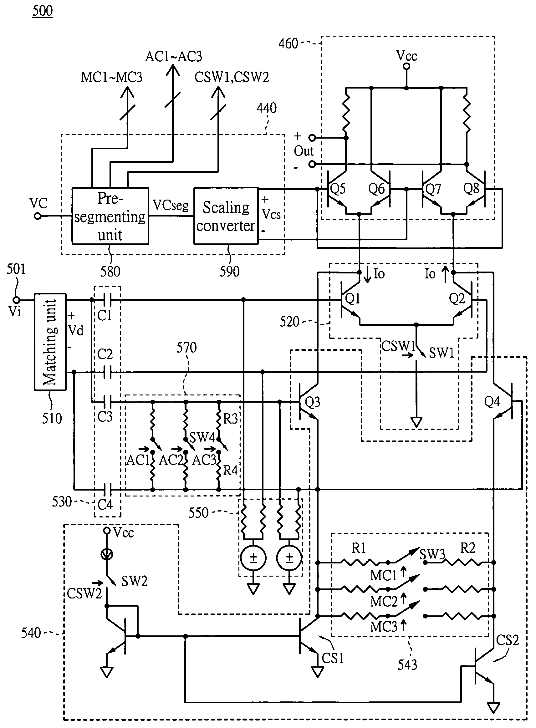
[0025]FIG. 4 is a block diagram showing the system of the variable-gain wide-dynamic-range amplifier according to an embodiment of the invention. The variable-gain wide-dynamic-range amplifier 400 in FIG. 4 includes an amplifier module 420, a control unit 440, and an output current regulating circuit 460. The amplifier module 420 amplifies an input signal Vi. The amplifier module 420 includes several amplifier units 422 which are coupled to each other in parallel. The gains of the amplifier units 422 are different. The control unit 440 enables at least one of the amplifier units 422 according to a gain control signal VC. The at least one of the amplifier units 422 which is enabled outputs a current signal lo in response to the input signal Vi. The output current regulating circuit 460 receives the current signal lo which is outputted from the at least one amplifier units which is enabled. The output current regulating circuit 460 regulates the magnitude of the current signal lo unde...


PUM


Abstract

A variable-gain wide-dynamic-range amplifier including an amplifier module, a control unit, and an output current regulating circuit is provided. The amplifier module amplifies an input signal. The amplifier module includes several amplifier units coupled to each other in parallel. The gains of the amplifier units are different. The control unit enables at least one of the amplifier units according to a gain control signal. The at least one of the amplifier units which is enabled is for outputting a current signal in response to the input signal. The output regulating circuit is for receiving the current signal and outputting an output signal accordingly by regulating the magnitude of the current signal under the control of the control unit. Each of the amplifier units is coupled to the output current regulating circuit in series. The control unit is for controlling the output current regulating circuit according to the gain control signal.

Description

[0001]This application claims the benefit of Taiwan application Serial No. 96148033, filed Dec. 14, 2007, the subject matter of which is incorporated herein by reference.BACKGROUND OF THE INVENTION[0002]1. Field of the Invention[0003]This invention relates in general to an amplifier, and more particularly to a variable-gain wide-dynamic-range amplifier.[0004]2. Description of the Related Art[0005]In the field of communication, a receiver, for receiving signal, ordinarily adopts variable gain amplifier to amplify the signal being received. When the magnitude of the received input signal varies, the gain of an amplifier will be regulated accordingly to maintain proper magnitude of the output signal.[0006]FIG. 1 is a circuit diagram showing a conventional variable gain amplifier using a current steering circuit. The variable gain amplifier 100 uses the current steering circuit 140 to regulate the gain of the amplifier 100 according to the voltage of the control signal VCTL. When the ma...

Claims


Application Information

Patent Timeline
IPC IPC(8): H03G3/30H03F3/45
CPCH03F1/3211H03F3/45089H03F3/45098H03F3/72H03F2203/45244H03F2203/45366H03G1/0088H03F2203/45492H03F2203/45544H03F2203/45576H03F2203/45616H03F2203/7236H03G1/0035H03F2203/45392
Inventor LEE, CHING-FENG
Owner IND TECH RES INST
Why Eureka
Try Eureka