Single drive betatron

Active Publication Date: 2009-06-18
SCHLUMBERGER TECH CORP
View PDF41 Cites 8 Cited by
  • Summary
  • Abstract
  • Description
  • Claims
  • Application Information

AI Technical Summary

Benefits of technology

[0015]Operation of this betatron includes forming a first magnetic flux of a first polarity that passes through the guide magnet, the electron acceleration passageway and the core and then returns through the return yokes, and a second magnetic flux of either the first polarity or of an opposing second polarity that passes through the core and returns through the guide magnet gap and the electron acceleration passageway. At the beginning of each cycle, a high voltage pulse (typically a few kV) is applied to the injector and causes electrons to be injected into the electron acceleration passageway. To achieve fast contraction without compromising the maximum energy the core is a hybrid

Problems solved by technology

These sources pose a radiation hazard and require strict controls to prevent accidental exposure or intentional misuse.
In addition, most sources have a long half life and disposal is a significant issue.
Satisfying the betatron condition does not insure the machine will work.
Charge trapping, injecting electrons into the betatron orbit at the optimal point of time, is another cha

Method used


Image

  • Single drive betatron
  • Single drive betatron
  • Single drive betatron

Examples


Embodiment Construction

[0031]The particulars shown herein are by way of example and for purposes of illustrative discussion of the embodiments of the present invention only and are presented in the cause of providing what is believed to be the most useful and readily understood description of the principles and conceptual aspects of the present invention. In this regard, no attempt is made to show structural details of the present invention in more detail than is necessary for the fundamental understanding of the present invention, the description taken with the drawings making apparent to those skilled in the art how the several forms of the present invention may be embodied in practice. Further, like reference numbers and designations in the various drawings indicated like elements.

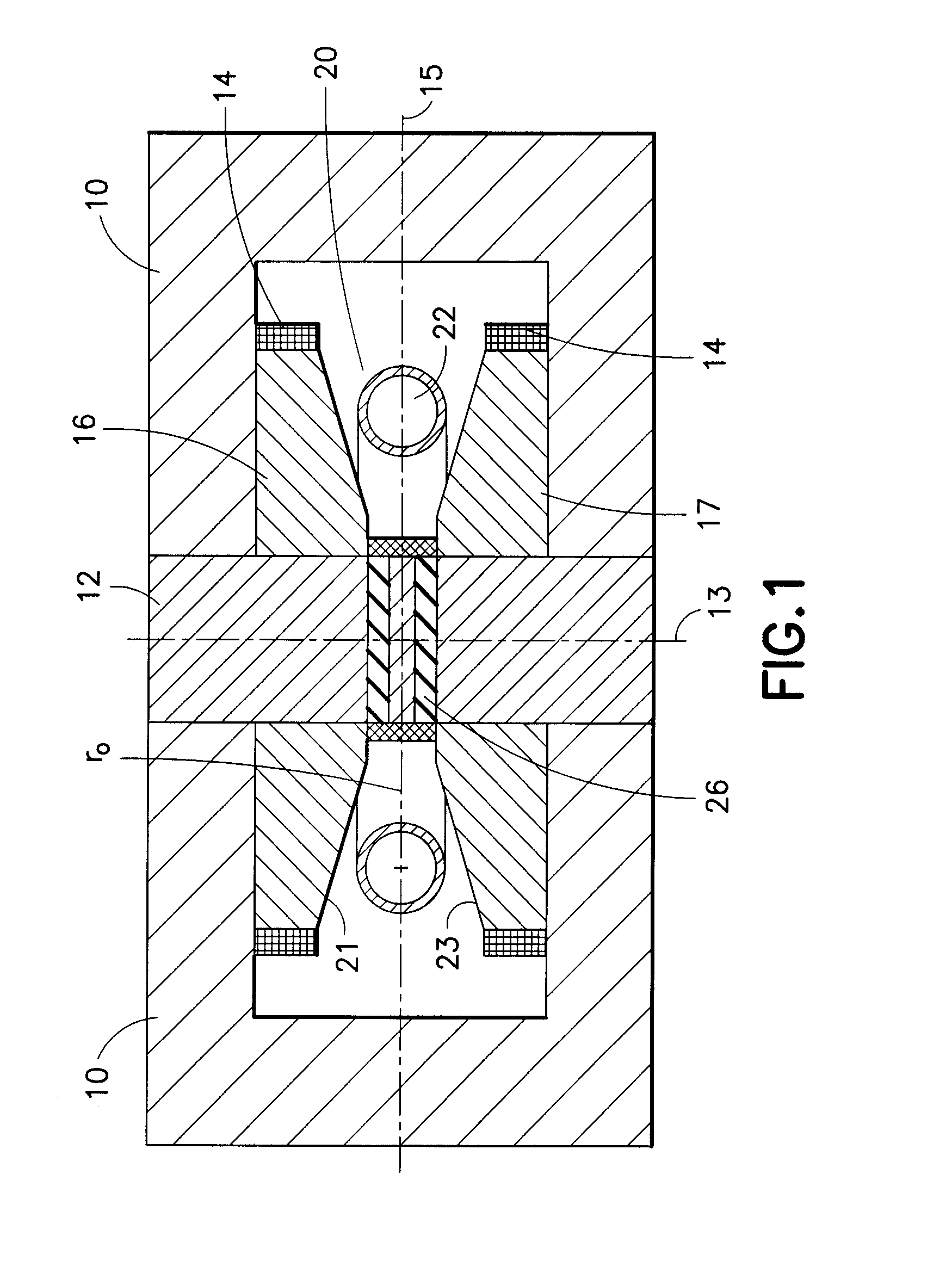
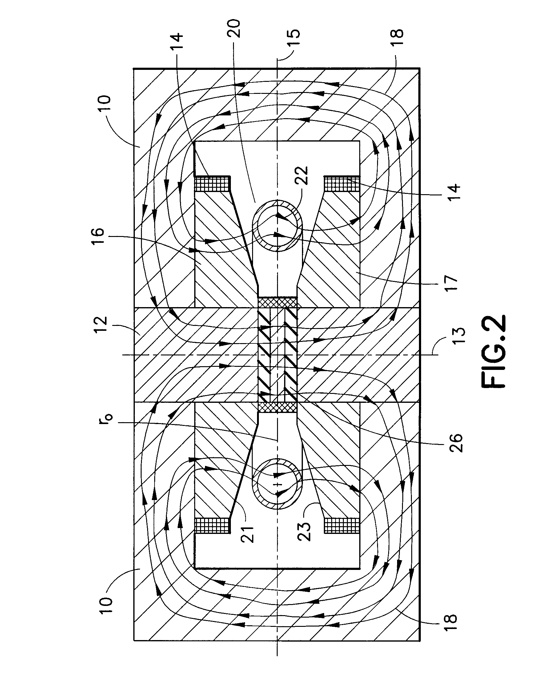
[0032]According to an embodiment of the invention, the invention includes a betatron magnet includes a circular, donut shaped guide magnet and a core disposed in the center and abutting the guide magnet, and one or more perip...


PUM


Abstract

A betatron includes a betatron magnet with a first guide magnet having a first pole face and a second guide magnet having a second pole face. Both the first and the second guide magnet have a centrally disposed aperture and the first pole face is separated from the second pole face by a guide magnet gap. A core is disposed within the centrally disposed apertures in an abutting relationship with both guide magnets. The core has at least one core gap. A drive coil is wound around both guide magnet pole faces. An orbit control coil has a contraction coil portion wound around the core gap and a bias control portion wound around the guide magnet pole faces. The contraction coil portion and the bias control portion are connected but in opposite polarity. Magnet fluxes in the core and guide magnets return through peripheral portions of the betatron magnet.

Description

CROSS REFERENCE TO RELATED APPLICATION(S)[0001]This patent application is related to commonly owned U.S. patent application Ser. No. Attorney Docket 49.0348 US NP, titled “Bi-Directional Dispenser Cathode”; Luke T. Perkins, filed on Dec. 14, 2007.BACKGROUND OF THE INVENTION[0002]1. Field of the Invention[0003]This invention generally relates to a compact betatron electron accelerator. More particularly, a single coil drives both a core section and a guide field eliminating a need for, and space occupied by, separate drive coils separated by an air gap.[0004]2. Background of the Invention[0005]Oil well bore hole logging is a process by which properties of earth strata as a function of depth in the bore hole are measured. A geologist reviewing the logging data can determine the depths at which oil containing formations are most likely located. One important piece of the logging data is the density of the earth formation. Most present day well logging relies on gamma-rays obtained from...

Claims


Application Information

Patent Timeline
IPC IPC(8): H05H11/00H01J35/00H01F7/06
CPCH05H11/04H05H11/00
Inventor CHEN, FELIX
Owner SCHLUMBERGER TECH CORP
Why Eureka
Try Eureka