
Near-field gap pull-in method and optical disc apparatus therefor

a pull-in method and optical disc technology, applied in the direction of digital signal error detection/correction, instruments, recording signal processing, etc., can solve the problems of gap error signal change, disc may collide with disc, overshoot, etc., and achieve the effect of stably performing

Inactive Publication Date: 2009-06-18
SAMSUNG ELECTRONICS CO LTD
View PDF7 Cites 6 Cited by
  • Summary
  • Abstract
  • Description
  • Claims
  • Application Information

AI Technical Summary

Benefits of technology

[0008]Aspects of the present invention provide a gap pull-in method capable of stably performing gap pull-in during a section where a gap error signal changes linearly and an optical disc apparatus therefor.

Problems solved by technology

However, because the gap distance is very small, for example, several tens of nm as described above, when overshoot occurs during gap pull-in, the SIL may collide with a disc.
The overshoot may occur, for example, due to decrease in the dynamic characteristics of the actuator or contamination of the SIL.
In addition, as each disc has different reflectivity, the gap error signal changes, and stability is reduced when controlling gap servo depending on the gap distance.

Method used


Image

  • Near-field gap pull-in method and optical disc apparatus therefor
  • Near-field gap pull-in method and optical disc apparatus therefor
  • Near-field gap pull-in method and optical disc apparatus therefor

Examples


Embodiment Construction

[0020]Reference will now be made in detail to the present embodiments of the present invention, examples of which are illustrated in the accompanying drawings, wherein like reference numerals refer to the like elements throughout. The embodiments are described below in order to explain the present invention by referring to the figures.

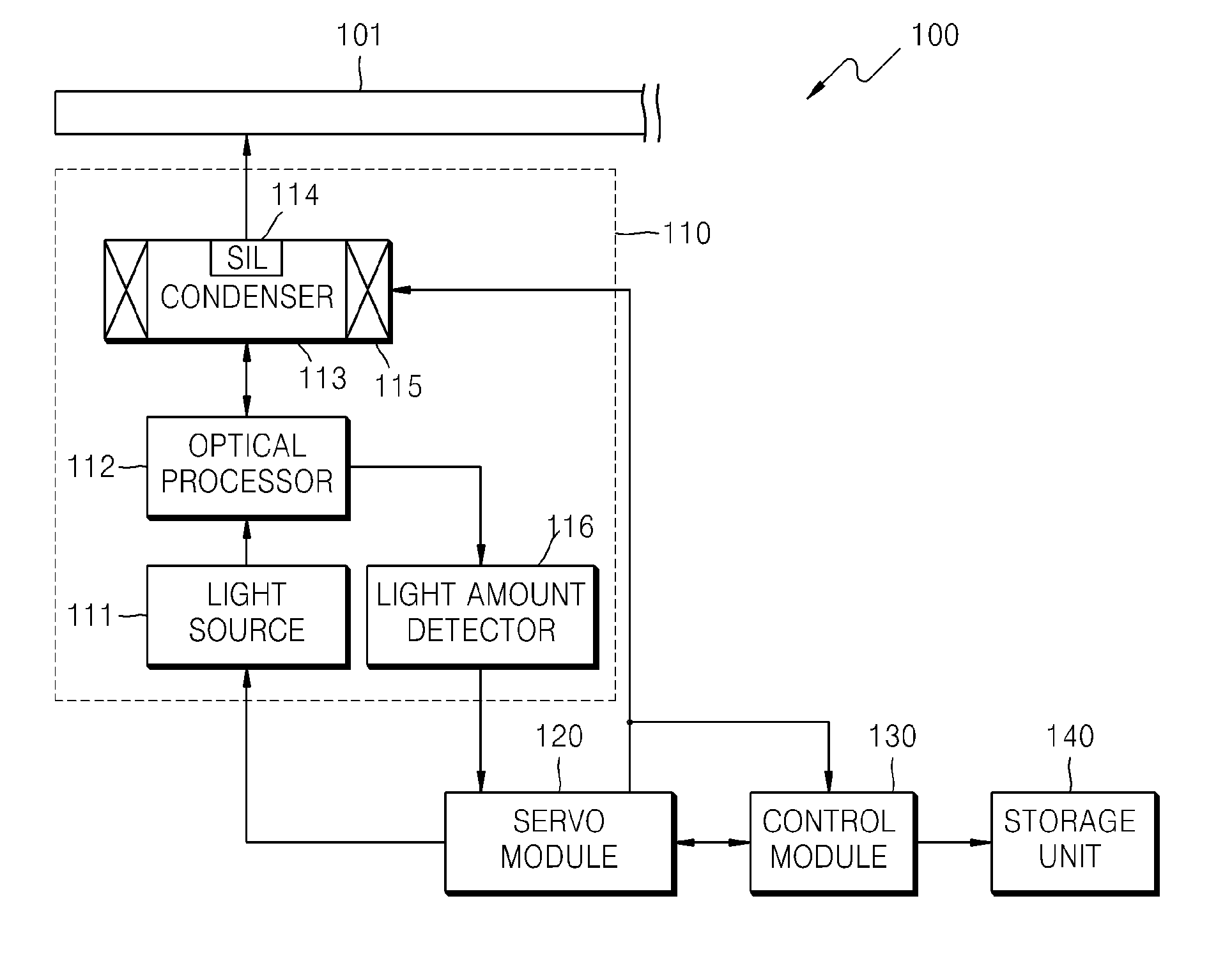
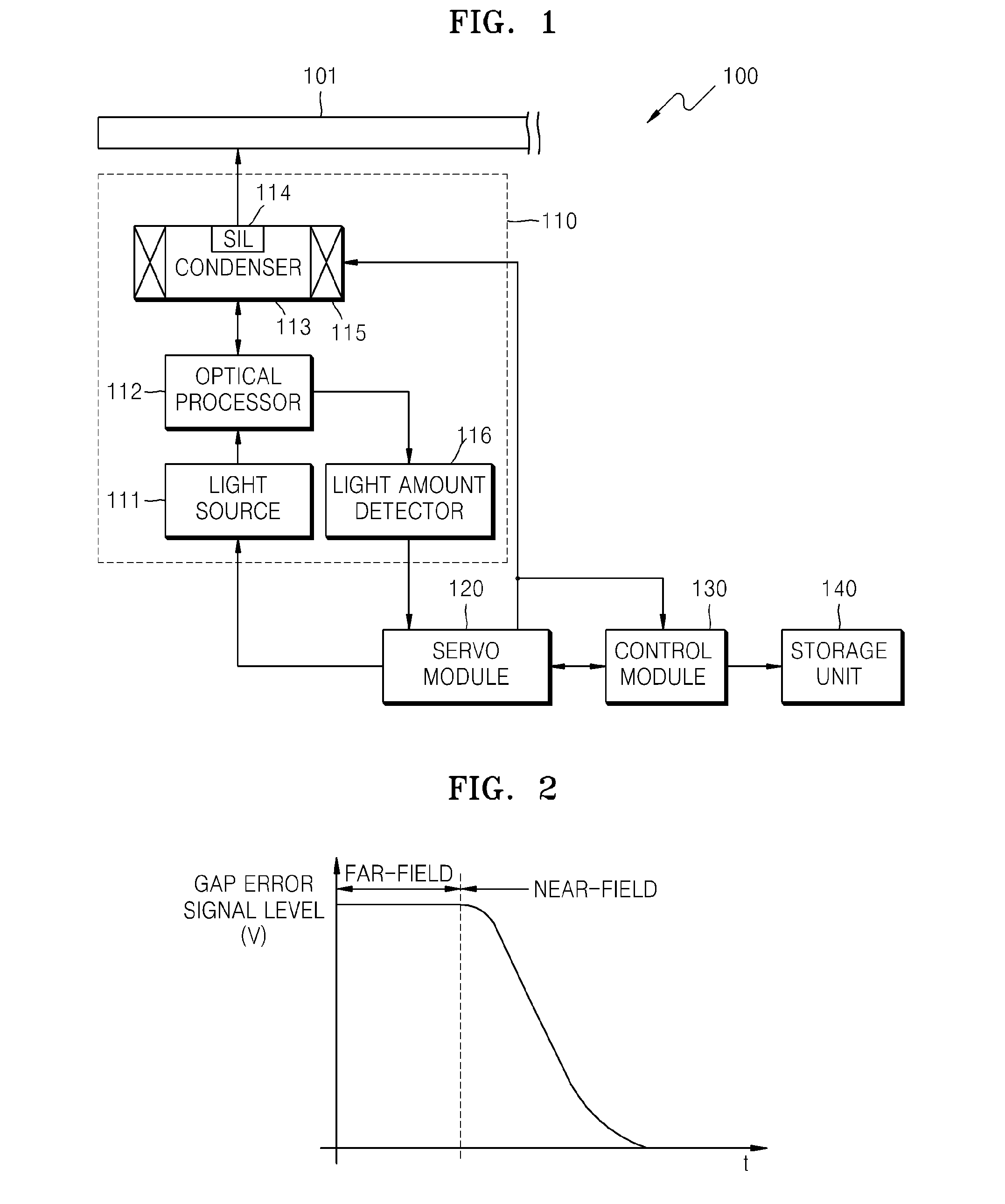
[0021]FIG. 1 is a schematic view of a near-field optical disc apparatus 100 according to an example embodiment of the present invention. The near-field optical disc apparatus 100 includes an optical head 110, a servo module 120, a control module 130, and a storage unit 140. According to other aspects of the present invention, the near-field optical disc apparatus 100 may include additional and / or different units. Similarly, two or more of the above units may be integrated into a single component. The optical head 110 includes a light source 111, an optical processor 112, a condenser 113 including a solid immersion lens (SIL) 114, an actuator 115, and a...


PUM

PropertyMeasurementUnit
gap distanceaaaaaaaaaa
driving voltageaaaaaaaaaa

Abstract

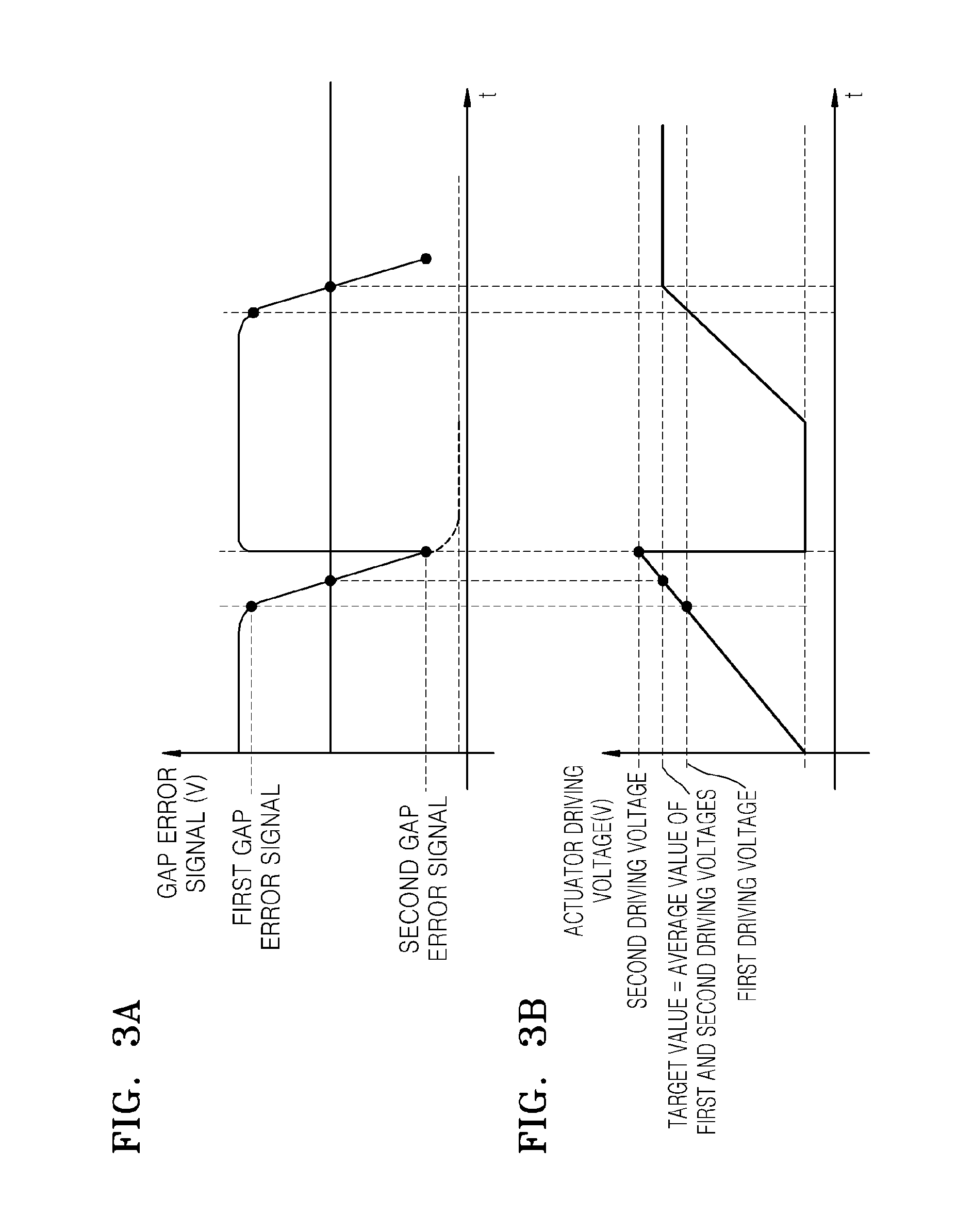
A gap pull-in method and an optical disc apparatus. Whether light condensed on a disc as an actuator ascends is near-field light is determined using a gap error signal. The range of an actuator driving voltage value during a section where the decrease rate of the gap error signal is constant is obtained when it is determined that the light condensed on the disc is near-field light. Gap pull-in is performed on the disc during a section where the actuator driving voltage value is within the obtained range.

Description

CROSS-REFERENCE TO RELATED APPLICATION[0001]This application claims all benefits accruing under 35 U.S.C. §119 from Korean Patent Application No. 2007-128754, filed on Dec. 12, 2007, in the Korean Intellectual Property Office, the disclosure of which is incorporated herein by reference.BACKGROUND OF THE INVENTION[0002]1. Field of the Invention[0003]Aspects of the present invention relate to a gap pull-in method and an optical disc apparatus therefor, and more particularly, to a method of performing gap pull-in more stably by preventing corruption with a disc in a near-field and an optical disc apparatus therefor.[0004]2. Related Art[0005]A near-field optical disc apparatus achieving large capacity and high data transfer rate (DTR) has recently been proposed. The near-field optical disc apparatus is also called a near-field recording system. The near-field optical disc apparatus records data on a disc or reproduces data from the disc using light in a near-field in which light diffrac...

Claims


Application Information

Patent Timeline
Patent Type & Authority Applications(United States)
IPC IPC(8): G11B7/00
CPCG11B2007/13727G11B7/0908G11B11/24G11B7/09G11B7/095
Inventor JEONG, AN-SIKSHIN, JONG-HYUNLEE, KYUNG-GEUNOTSUKA, TATSUHIRO
Owner SAMSUNG ELECTRONICS CO LTD
Learn More