Deposition apparatus

a technology of deposition apparatus and substrate, which is applied in the direction of chemical vapor deposition coating, coating, coating process, etc., can solve the problems of adversely affecting the quality of a thin film deposited on the substrate and the productivity of the deposition apparatus, temperature distribution across the substrate, and affecting the uniformity of a thin film

Active Publication Date: 2009-06-18
ASM KOREA LTD
View PDF94 Cites 402 Cited by
  • Summary
  • Abstract
  • Description
  • Claims
  • Application Information

AI Technical Summary

Problems solved by technology

Such an undesired film or impurity particles may contaminate the reaction chamber, adversely affecting the quality of a thin film deposited on the substrate and the productivity of the deposition apparatus.
Accordingly, temperature distribution across the substrate 156 may be non-uniform, adversely affecting the uniformity of a thin film deposited on the substrate 156.

Method used


Image

  • Deposition apparatus
  • Deposition apparatus
  • Deposition apparatus

Examples


examples 1 and 2

[0074]Referring to FIG. 5A and FIG. 5B, properties of a thin film deposited by the deposition apparatuses of FIGS. 1 and 3 will be described below. In Examples 1 and 2, ruthenium oxide (RuOx) thin films were deposited.

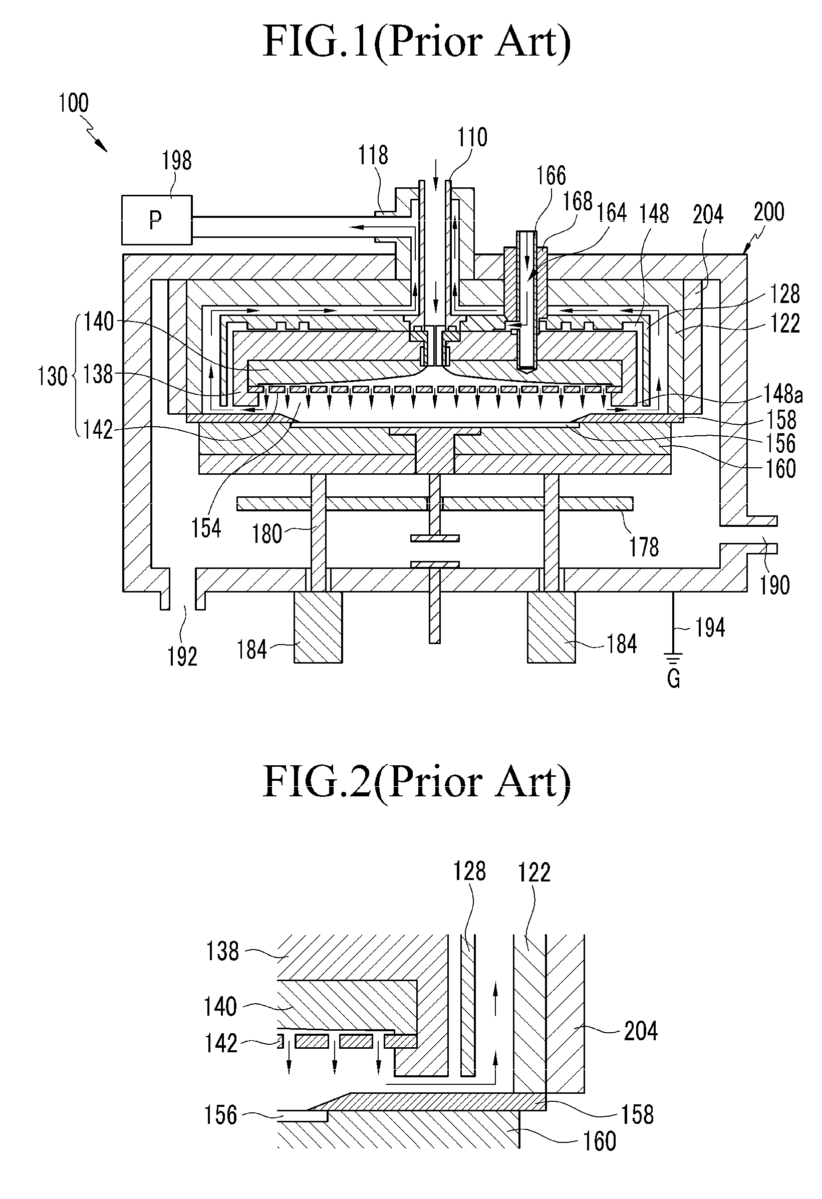
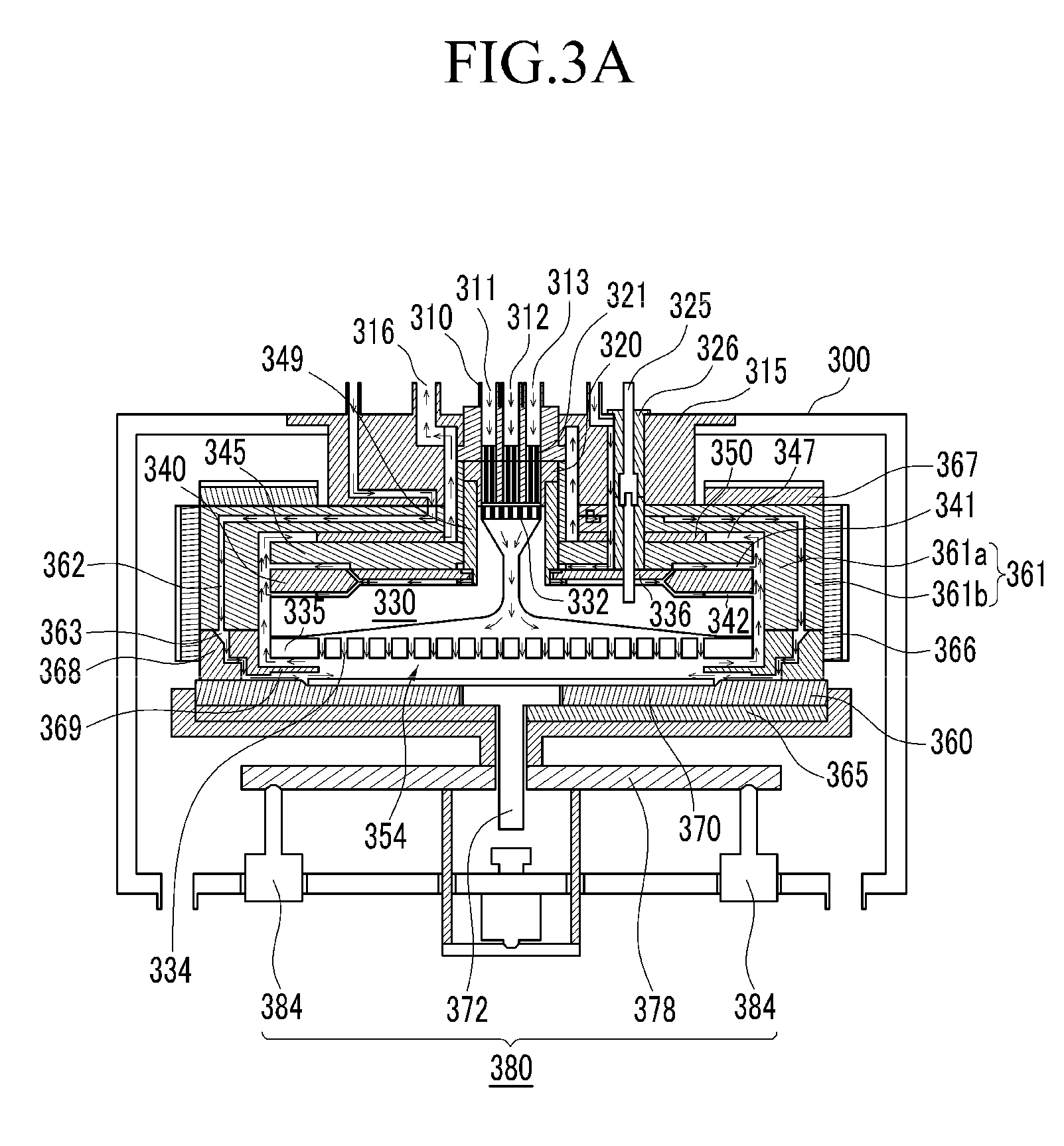
[0075]In Example 1, the conventional deposition apparatus of FIG. 1 was used. In Example 1, the gas blocking clamp contacted the substrate during the deposition process. In Example 2, the deposition apparatus of FIG. 3 was used. In Example 2, the gas blocking clamp was spaced apart from the substrate. An inert gas was supplied between the gas blocking clamp and the substrate. In the Examples 1 and 2, other deposition conditions were the same as each other.

[0076]After depositing the ruthenium oxide thin films, sheet resistances of the ruthenium oxide thin film were measured at 17 different positions on each of the ruthenium oxide thin films. Difference in sheet resistance between the different positions were calculated. The results are shown in FIG. 5A and FIG. 5B. FIG....

examples 3 and 4

[0078]Referring to FIG. 6A and FIG. 6B, uniformity of a thin film deposited by the deposition apparatuses of FIGS. 1 and 3 will be described below. FIG. 6A and FIG. 6B are photographs showing surfaces of ruthenium oxide (RuOx) thin films deposited by using the deposition apparatuses.

[0079]In Examples 3 and 4, thin films were deposited using the deposition apparatuses of FIG. 1 and FIG. 3, respectively. In Example 3, the conventional deposition apparatus of FIG. 1 was used. In Example 3, the gas blocking clamp contacted the substrate during the deposition process. In Example 4, the deposition apparatus of FIG. 3 was used. In Example 4, the gas blocking clamp was spaced apart from the substrate. An inert gas was supplied between the gas blocking clamp and the substrate. In the Examples 3 and 4, other deposition conditions were the same as each other.

[0080]After depositing the thin films, the surfaces of the deposited film were photographed. Photographs of the surfaces are shown in FIG...


PUM

PropertyMeasurementUnit
heightaaaaaaaaaa
distanceaaaaaaaaaa
diameteraaaaaaaaaa

Abstract

A deposition apparatus configured to form a thin film on a substrate includes: a reactor wall; a substrate support positioned under the reactor wall; and a showerhead plate positioned above the substrate support. The showerhead plate defines a reaction space together with the substrate support. The apparatus also includes one or more gas conduits configured to open to a periphery of the reaction space at least while an inert gas is supplied therethrough. The one or more gas conduits are configured to supply the inert gas inwardly toward the periphery of the substrate support around the reaction space. This configuration prevents reactant gases from flowing between a substrate and the substrate support during a deposition process, thereby preventing deposition of an undesired thin film and impurity particles on the back side of the substrate.

Description

CROSS-REFERENCE TO RELATED APPLICATIONS[0001]This application claims priority to and the benefit of Korean Patent Application No. 10-2007-0133428 filed in the Korean Industrial Property Office on Dec. 18, 2007, the entire contents of which are incorporated herein by reference.BACKGROUND[0002]1. Field of the Invention[0003]The present invention relates to a deposition apparatus. More particularly, the present invention relates to a deposition apparatus for preventing undesired deposition on the back side of a substrate.[0004]2. Description of the Related Art[0005]In manufacturing semiconductor devices, various apparatuses and processes have been developed to provide a high quality thin film on a substrate. Several methods have been used to form a thin film, employing surface reaction of a semiconductor substrate. The methods include vacuum evaporation deposition, Molecular Beam Epitaxy (MBE), different variants of Chemical Vapor Deposition (CVD) (including low-pressure and organometa...

Claims


Application Information

Patent Timeline
Patent Type & Authority Applications(United States)
IPC IPC(8): H01L21/30C23C16/54
CPCC23C16/45519C23C16/4408C23C16/40H01L21/205
Inventor PARK, HYUNG SANGCHOI, SEUNG WOOKIM, JONG SUJUNG, DONG RAKLEE, JEONG HOLEE, CHUN SOO
Owner ASM KOREA LTD
Why Eureka
Try Eureka