Method and apparatus for air-coupled transducer

a transducer and air-coupled technology, applied in the direction of generator/motor, mechanical vibration separation, instruments, etc., can solve the problems of narrow bandwidth operation success, limiting the overall bandwidth of the device, and acoustic impedance mismatch, etc., to achieve wideband frequency response, high signal amplitude, and rapid inspection speed

Inactive Publication Date: 2009-06-25
IOWA STATE UNIV RES FOUND
View PDF6 Cites 13 Cited by
  • Summary
  • Abstract
  • Description
  • Claims
  • Application Information

AI Technical Summary

Benefits of technology

[0008]Therefore it is a primary object, feature, or advantage of the present invention to improve over the state of the art.
[0009]It is a further object, feature, or advantage of the present invention to provide an air-coupled transducer using a spherical radiating surface that does not require mirrors, zone plates or any similar external devise to effect focusing.
[0010]It is a still further object, feature, or advantage of the present invention is to provide an air-coupled transducer that provides for native focusing.
[0011]A still further object, feature, or advantage of the present invention is to provide an air-coupled transducer that provides no contact inspection, no impedance matching layer requirement, rapid inspection speed and wideband frequency response.
[0012]A further object, feature, or advantage of the present invention is to provide an air-coupled transducer having native focusing that provides higher signal amplitude, improved imaging capability and wide spatial bandwidth.
[0013]Another object, feature, or advantage of the present invention is to provide an air-coupled transducer that provides for focusing without aberrations.

Problems solved by technology

When a PZT transducer is used as a primary probe in air, it encounters very large acoustic impedance mismatch at the boundary between the piezoelectric element and the surrounding air or gas boundary.
Attempts to remedy this problem have been limited to success in narrow bandwidth operations.
In addition, the application of a matching layer limits the overall bandwidth of the device.
Mirrors provide only limited bandwidth and leave one dimension unfocused.
Still, the Fresnel zone plate approach has inherent narrowband frequency response, image degradation by the generation of side lobes, and no specific design guidelines to decide radii of zone plates for ultrasound.
Si-wafers have proven difficult to handle owing to the fragility and brittleness of the silicon.
They also leave one dimension unfocused and suffer from bandwidth limitations.
Because brittle silicon wafers have customarily been used to fabricate a focused ultrasonic transducer capacitor, little progress has been made in the development of a new backplate material.
Therefore, the challenge still remains to fabricate a focused capacitive ultrasonic transducer.

Method used


Image

  • Method and apparatus for air-coupled transducer
  • Method and apparatus for air-coupled transducer
  • Method and apparatus for air-coupled transducer

Examples


Embodiment Construction

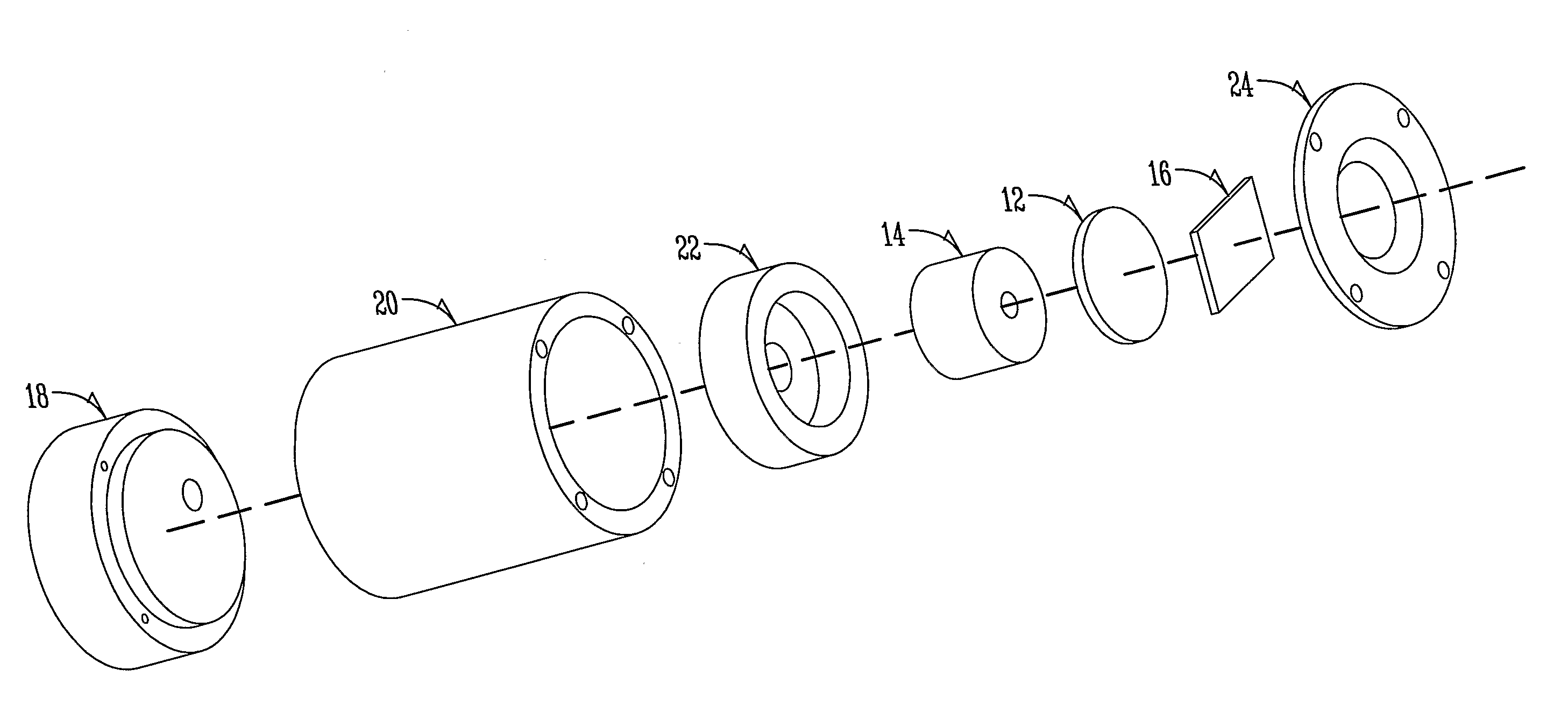
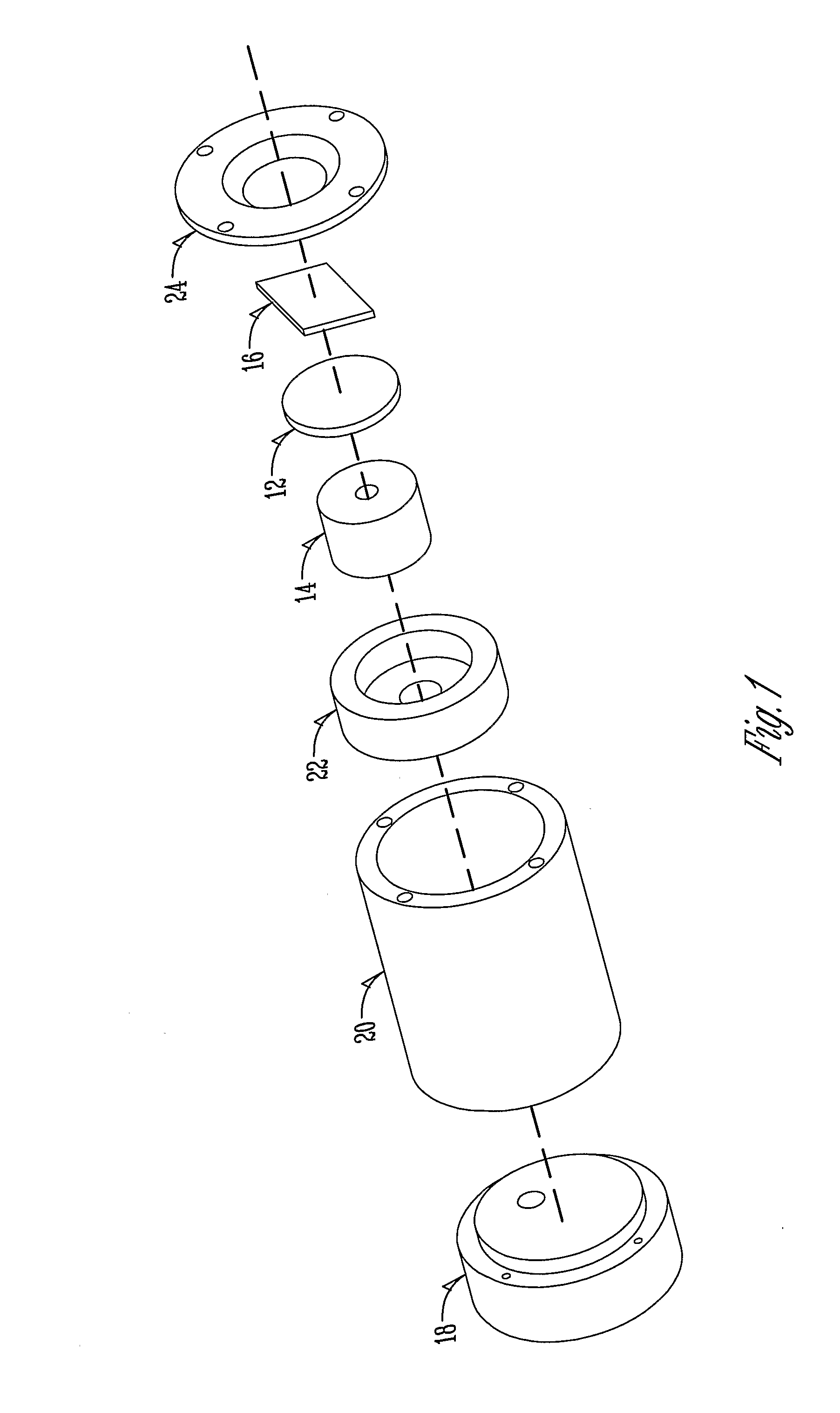
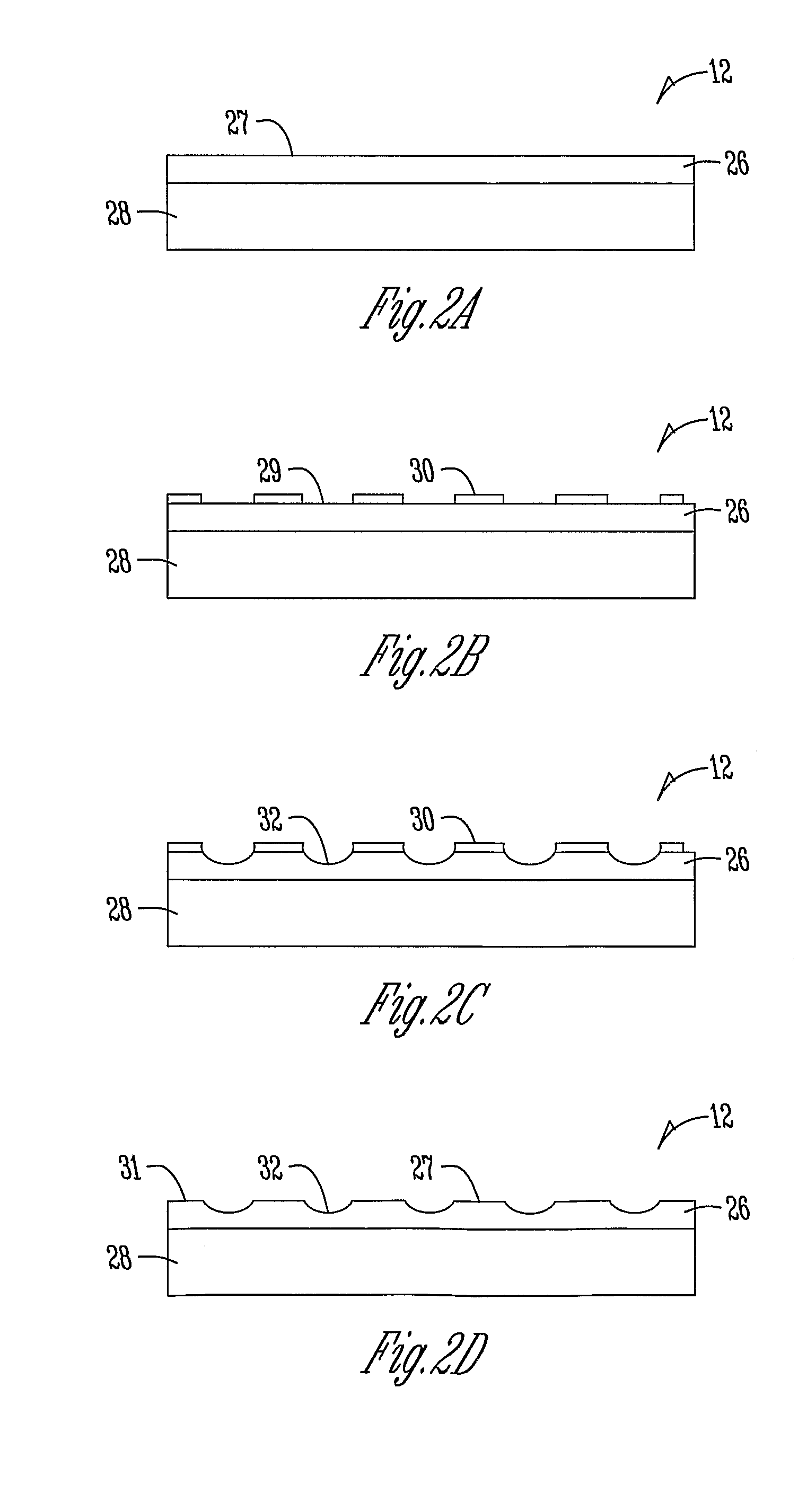
[0045]The present invention includes a number of aspects all of which have broad and far-reaching application. Although specific embodiments are described herein, the present invention is not to be limited to these specific embodiments. One aspect of the invention relates to the use of a flexible backplate in an air-coupled ultrasonic transducer. The flexible backplate allows it to conform to a number of different geometries, including, but not limited to a spherical shape.

[0046]Turning now to the drawings in which similar reference characters denote similar elements through the several views. Illustrated in FIGS. 1-10 is the combination of various views and in-use configurations of the transducer. The transducer being described with particularity herein.

Principles of Operation

[0047]FIG. 1 is an isometric view of the transducer. The process of generating and receiving ultrasound is very similar to the working principles of a condenser microphone. As shown in FIG. 1, an air coupled t...


PUM

PropertyMeasurementUnit
diameteraaaaaaaaaa
focal lengthaaaaaaaaaa
thickaaaaaaaaaa

Abstract

An air-coupled transducer includes a ultrasonic transducer body having a radiation end with a backing fixture at the radiation end. There is a flexible backplate conformingly fit to the backing fixture and a thin membrane (preferably a metallized polymer) conformingly fit to the flexible backplate. In one embodiment, the backing fixture is spherically curved and the flexible backplate is spherically curved. The flexible backplate is preferably patterned with pits or depressions.

Description

CROSS-REFERENCE TO RELATED APPLICATIONS[0001]This application is a conversion of and claims priority to U.S. Provisional Patent Application No. 60 / 683,840 filed May 24, 2005, which is herein incorporated by reference in its entirety.GRANT REFERENCE[0002]The work presented in this application was supported in part by a federal grant from the NASA Grant No. NAG102098. The government may have certain rights in this invention.BACKGROUND OF THE INVENTION[0003]More recently, non-contact inspection methods in nondestructive evaluation (NDE) have been receiving substantial attention compared with contact or liquid-coupled inspection methods. In particular, it is more practical and efficient to employ a non-contact inspection method if the article under inspection is wood, paper product, porous material, or hot metallic material. Unlike the contact inspection methods, the non-contact inspection methods use only gas or air as a coupling medium, so that there are no risks of contamination of t...

Claims


Application Information

Patent Timeline
Patent Type & Authority Applications(United States)
IPC IPC(8): G01N29/00H04R31/00
CPCB06B1/0292Y10S310/80Y10T29/49005
Inventor SONG, JUNHOCHIMENTI, DALE E.
Owner IOWA STATE UNIV RES FOUND
Why Eureka
Try Eureka