Camshaft adjustment device

a technology of camshaft and adjustment device, which is applied in the direction of valve drives, couplings, machines/engines, etc., can solve the problems of undesirable oil pressure drop below the required minimum pressure of the engine, engine life may be shortened, and the device design is compact, easy to manufacture, and cost-effective

Active Publication Date: 2009-06-25
DAIMLER AG
View PDF4 Cites 42 Cited by
  • Summary
  • Abstract
  • Description
  • Claims
  • Application Information

AI Technical Summary

Benefits of technology

[0014]Another advantage, particularly with respect to a fast adjustment at low oil temperatures and, at the same time, a compact design of the device is obtained if the hydraulic circuit includes a control valve with a control slide member integrated into the central mounting bolt of the adjustment device onto the driven shaft, and, at the same time, one or several check valves of the hydraulic circuit are also arranged within, or at, the central mounting bolt. This makes a particularly cost-effective and simple manufacture possible and facilitates the assembly of the adjustment device according to the invention.

Problems solved by technology

An adjustment of the hydraulic cam adjuster results normally in a pressure drop in the oil supply to the camshaft adjuster.
Consequently, at low engine speed and hot engine, operation of the camshaft adjuster may result in an undesirable oil pressure drop below the required minimum pressure of the engine.
As a result, for example, the camshaft bearings may wear excessively the engine life may be shortened.
This however increases the power consumption of accessory device and consequently the fuel consumption for a motor vehicle with the same driving performance.
Alternatively, pressure stores may be used which, however, require a larger space which is generally not available.
Particularly with high adjustment speeds, this may result in a drop of the engine oil pressure which, at low engine speeds and hot engine oil, may drop below the limit values.
Beginning at a certain maximum speed an adjustment is no longer possible.
The adjuster can be operated also at relatively low oil pressures because the pressure losses are minimized by short control lines, although a certain pressure drop is unavoidable.
This increases the number of components and, with more than two operating chambers, requires the provision of expensive oil channels and increases the manufacturing expenses.
An adjustment at higher engine speeds is possible with this circuit only in a limited way because of the mechanical inertia.
However, the additional valve with a separate electrical switching operation is disadvantageous as the adjuster and the respective motor control becomes more complicated and expensive.
The hydraulic actuation however requires a larger space because of the presence of a control valve, check valves and a switch-over valve in the camshaft adjuster.

Method used


Image

  • Camshaft adjustment device
  • Camshaft adjustment device
  • Camshaft adjustment device

Examples


Embodiment Construction

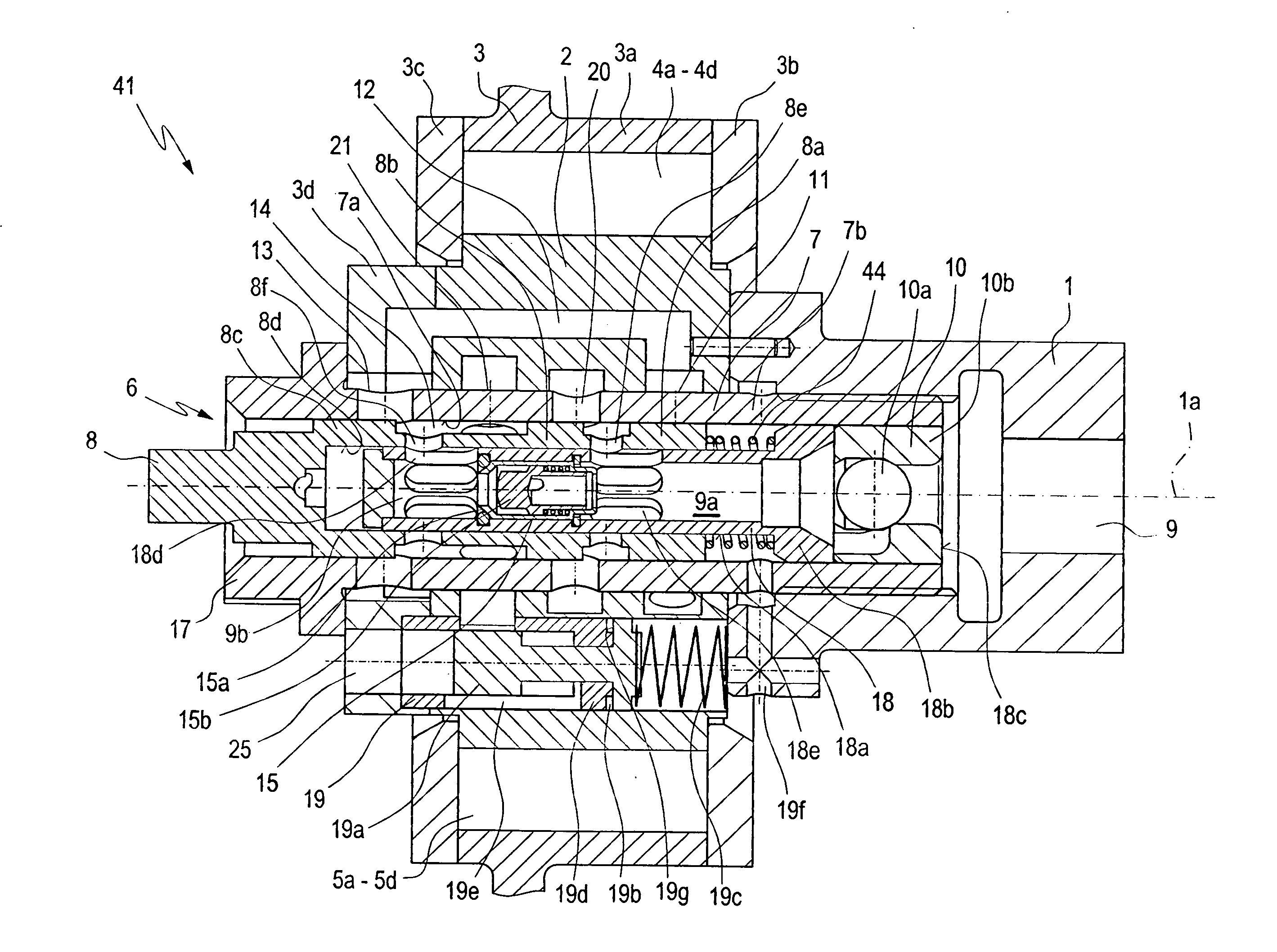
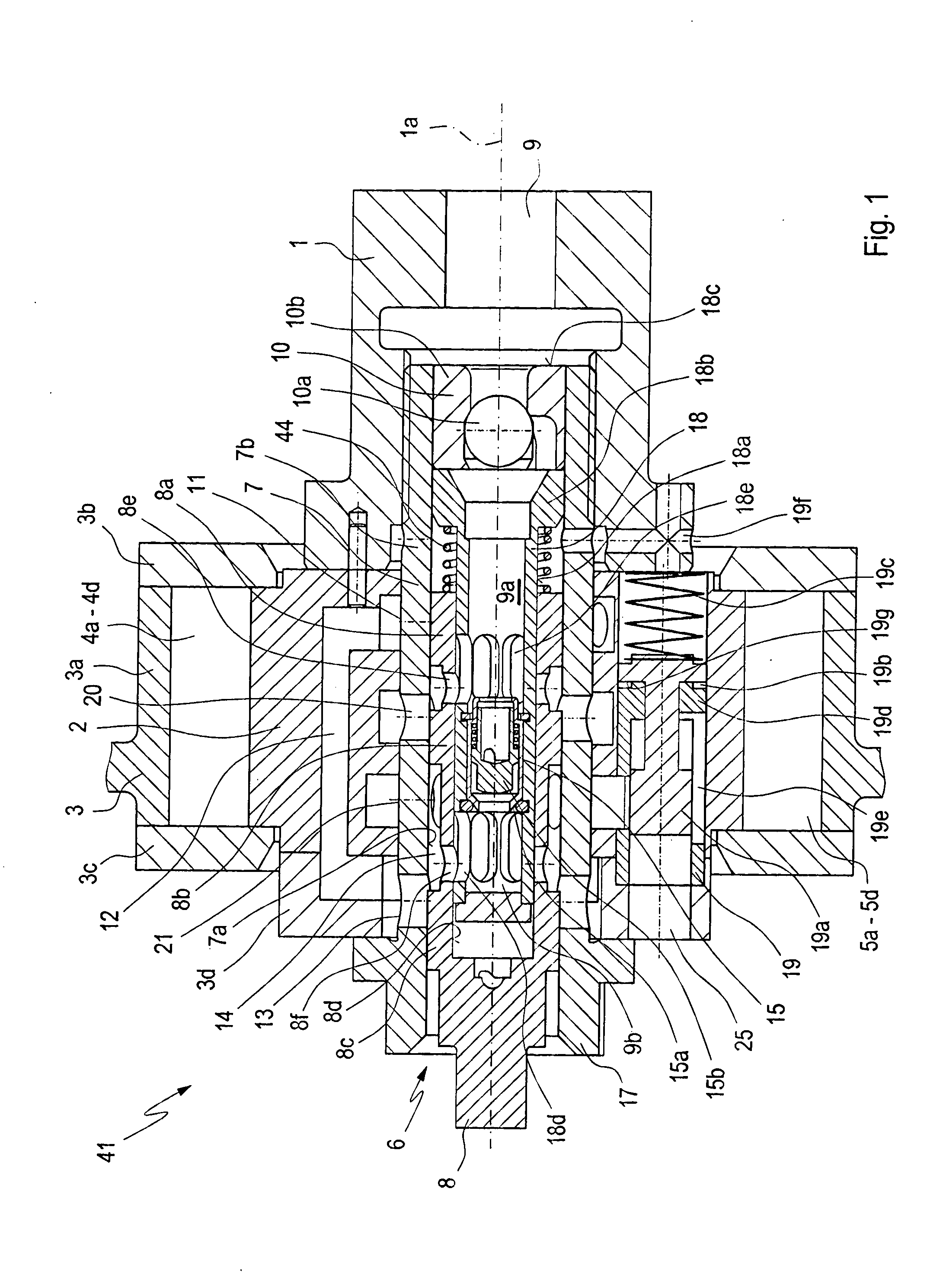
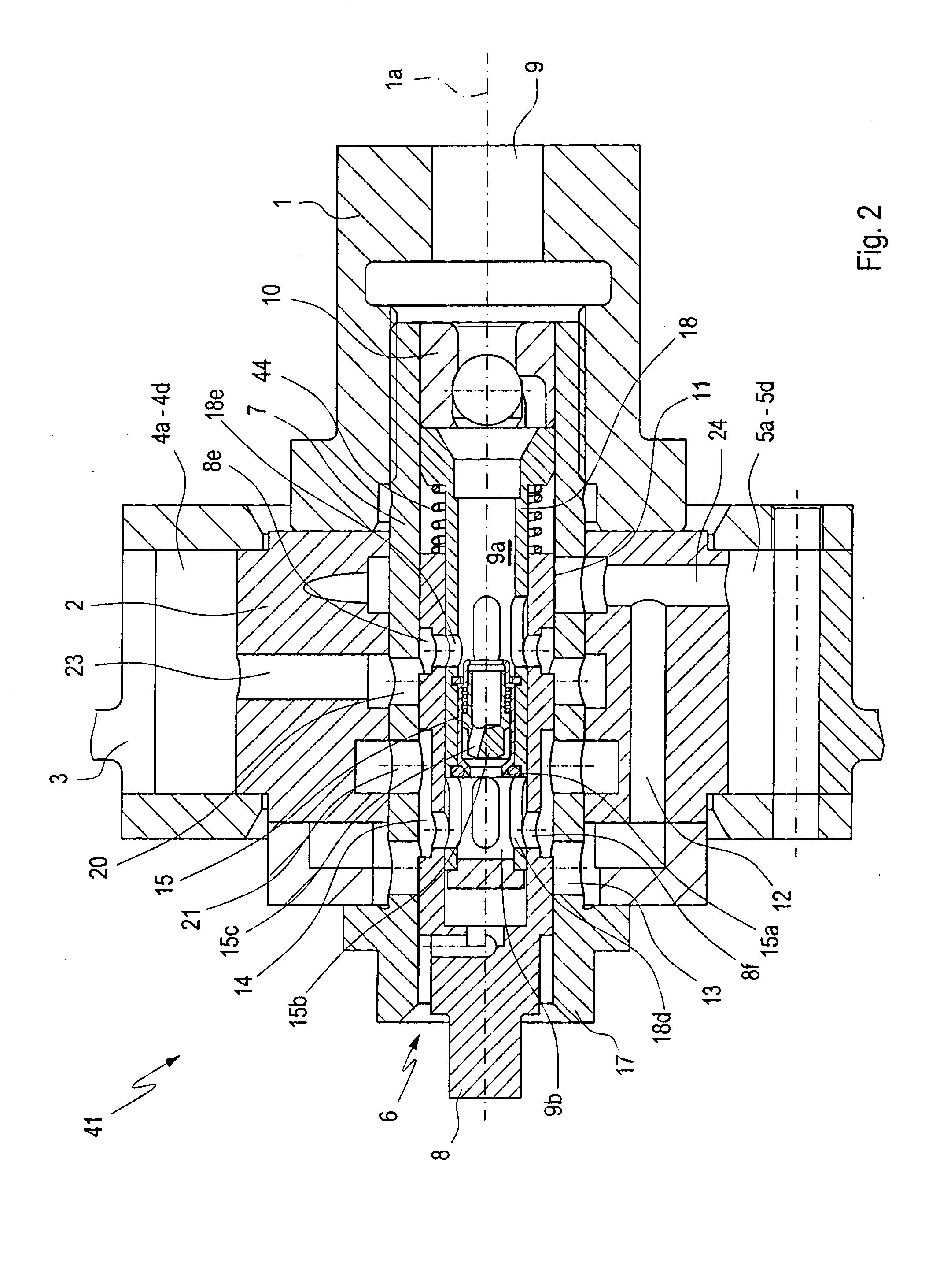
[0036]FIGS. 1 to 10 show an embodiment of an adjustment device according to the present invention for the adjustment of a phase position of a camshaft 1 with respect to a crankshaft of an internal combustion engine in different settings. The adjustment device is disposed in the drive train of a camshaft 1 driven by a crankshaft which is not shown in the drawings. The adjustment device is supplied with hydraulic fluid by the hydraulic system of an internal combustion engine in which the adjustment device is installed.

[0037]For adjusting the phase position or changing the phase position, the adjustment device includes a first inner body 2, which is mounted for rotation with the camshaft 1, and a second outer body 3 which is rotatably supported relative to the first body 2. Around the second body 3 extends a drive connection (not shown) to the crankshaft of the engine such as a drive chain. The second body 3 comprises several body parts 3a to 3d. The two bodies 2 and 3 together form gr...


PUM


Abstract

In an adjustment device for adjusting the phase position of a camshaft relative to a crankshaft of an internal combustion engine which includes a hydraulic system for supplying hydraulic fluid under pressure to the adjustment device for the controlled admission to, and release thereof from, operating chambers of the adjustment device under the control of a control device including a control valve, the operating chambers are in communication with one another via control valves to permit flow of hydraulic fluid from one set of operating chambers to another by the varying torques effective on the camshaft or by controlling fluid supply to the operating chambers from the hydraulic fluid supply system.

Description

BACKGROUND OF THE INVENTION[0001]The invention relates to camshaft adjustment device for the adjustment of a phase position of a camshaft relative to a crankshaft of an internal combustion engine which includes a hydraulic system for supplying hydraulic operating fluid to the operating chambers of the camshaft adjustment device.[0002]Adjustment devices for controlling the phase position of a camshaft relative to a crankshaft of an internal combustion engine often employ a hydraulic operating mechanism including vanes mounted on a first body which is rotatable with the camshaft and a second body which receives the first body so as to be rotatable therein and is provided with counter vanes. The two bodies form between the vanes operating chambers to which hydraulic operating fluid can be supplied. An adjustment of the hydraulic cam adjuster results normally in a pressure drop in the oil supply to the camshaft adjuster. Consequently, at low engine speed and hot engine, operation of the...

Claims


Application Information

Patent Timeline
Patent Type & Authority Applications(United States)
IPC IPC(8): F01L1/344
CPCF01L1/34409F01L2001/34446F01L2001/34426F01L1/3442
Inventor PAUL, ENRICOREUTER, UWERUDZINSKI, HOLGERSTUBBEMANN, ULRICH
Owner DAIMLER AG
Why Eureka
Try Eureka