Fresnel solar concentrator with internal-swivel and suspended swivel mirrors

Inactive Publication Date: 2009-06-25
RABINOWITZ MARIO
View PDF43 Cites 8 Cited by
  • Summary
  • Abstract
  • Description
  • Claims
  • Application Information

AI Technical Summary

Benefits of technology

[0050]In the Electric Wind and Internal-swivel Induced Dipole Alignment Adjustable Fresnel Planar Mirror Solar Concentrators that have been developed, the rotatable optical elements (mirrors) can be aligned to concentrate solar energy on a receiver having dimensions small compared to the dimensions of the array. This permits the focal point of the array to remain focused on the receiver over the course of a day and throughout the year. The swivel point for rotation is located above the mirrors, giving the additional advantage of vertical stability. Vertical stability provides a natural fiducial or starting point, as well as enabling simpler and more efficient alignment. At startup for initial operation, or following a blackout, having the swivel point affixed above the mirrors gives them a natural quasi-vertical position since the center of mass of the mirrors is below the swivel suspension point. A given natural angle with respect to the vertical can be built in to the mirrors by weight distribution and / or constructing the mirrors with a cocked angle relative to their support stem. Such quasi-vertical positioning allows the mirrors to start from a nearly aligned position, rather than having to move over a much larger angle for alignment. Futhermore, the natural stability of a quasi-vertical position [as opposed to the natural stability of a quasi-horizontal position when the swivel point is below the mirrors] permits a substantial reduction in the latching force required to hold the mirrors in alignment between alignment operations.

Problems solved by technology

No prior art was found that utilized induced dipole alignment in electric fields of swiveled mirrors that are vertically stable in a Fresnel reflector solar concentrator, optical switches, displays, or other similar equipment.

Method used


Image

  • Fresnel solar concentrator with internal-swivel and suspended swivel mirrors
  • Fresnel solar concentrator with internal-swivel and suspended swivel mirrors
  • Fresnel solar concentrator with internal-swivel and suspended swivel mirrors

Examples


Embodiment Construction

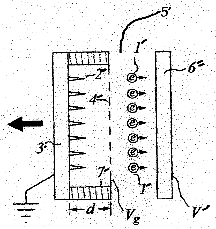
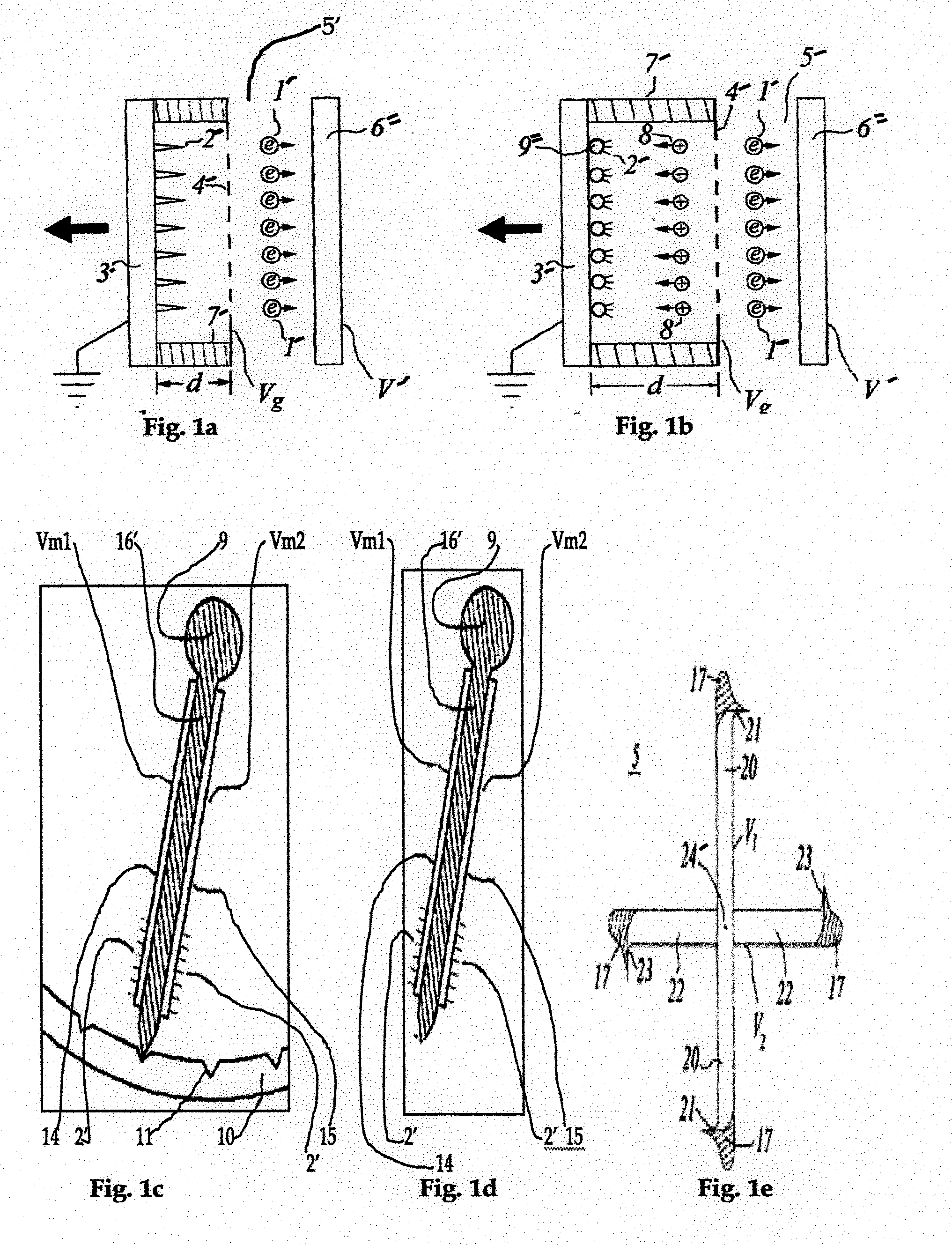
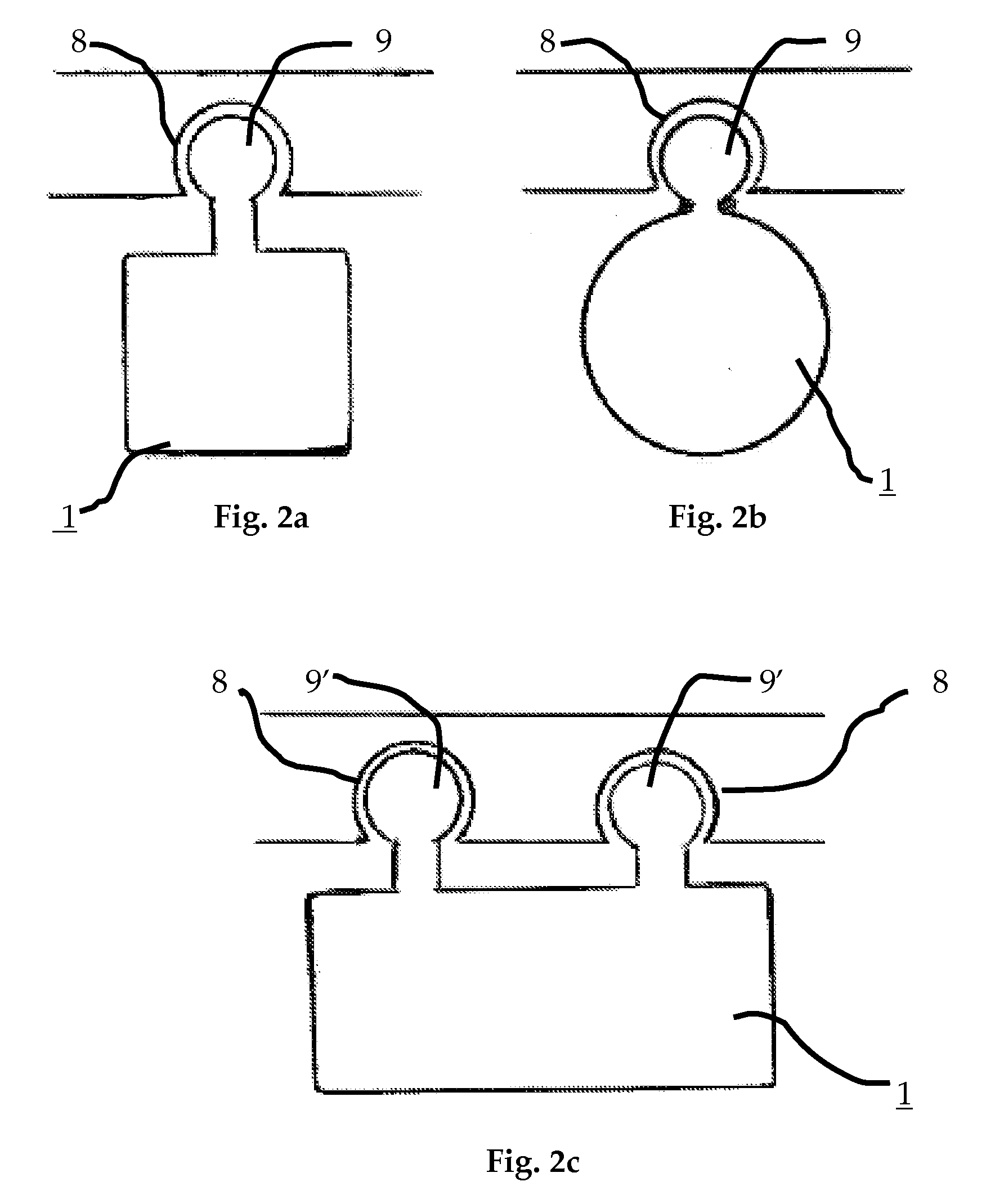
[0159]As is described here in detail, the objectives of the instant invention may be accomplished by any of a number of ways separately or in combination, as taught by the instant invention. A tracking solar concentrator has been developed in which the orientation of individual optical elements (mirrors, reflectors, lenses) is accomplished by electric wind and / or electric dipole interaction between the electric field of a grid and an induced dipole, and / or an electret dipole, to align them consecutively or concurrently without the need for expensive, bulky, and heavy motors. Thus the improved solar concentrator of the instant invention can be less expensive, more reliable, and lighter in weight than conventional solar arrays.

[0160]FIG. 1a shows a cross-sectional side view of one embodiment of an electric wind motive device for mirror alignment, which in this case produces a force by the emission of electrons 1′ from whiskers 2′ on an electrode 3′ that serves as cathode. Upon leavin...


PUM


Abstract

This invention deals with novel method and apparatus for positioning and motion control of the elements (mirrors) of a Fresnel reflector solar concentrator tracking heliostat array wherein the elements are suspended with the center of mass below the swivel point, or have an internal-swivel. This achieves an advantageous natural vertical stability. The torque to produce angular deflection, and rotational motion is provided separately by an electric wind force due to electrons, ions, and / or neutrals; or in combination with an induced and / or permanent dipole coupling to an electronic grid. Thus forces and torques are produced without the use of internal moving parts such as in motors. The instant invention exceeds the capability of conventional systems. It is ideally suited for maximization of solar energy focused by a low-profile concentrator array onto a receiver. Since there are no internal moving parts, the instant invention provides less costly and greater ease of manufacture. Dynamic motion can be controlled over a wide range of dimensions from nanometers to decimeters.

Description

INCORPORATION BY REFERENCE[0001]In a solar energy application (as well as other functions), adjustable reflecting elements are an important feature of a Fresnel reflector solar concentrator which tracks the sun and directs the sunlight to a receiver as described in the following patents and published papers. The following U.S. patents, and Solar Journal publication are fully incorporated herein by reference.[0002]1. U.S. Pat. No. 7,247,790 by Mario Rabinowitz, “Spinning Concentrator Enhanced Solar Energy Alternating Current Production” issued on Jul. 24, 2007.[0003]2. U.S. Pat. No. 7,187,490 by Mario Rabinowitz, “Induced Dipole Alignment Of Solar Concentrator Balls” issued on Mar. 6, 2007[0004]3. U.S. Pat. No. 7,133,183 by Mario Rabinowitz, “Micro-Optics Solar Energy Concentrator” issued on Nov. 7, 2006.[0005]4. U.S. Pat. No. 7,130,102 by Mario Rabinowitz, “Dynamic Reflection, Illumination, and Projection” issued on Oct. 31, 2006.[0006]5. U.S. Pat. No. 7,115,881 by Mario Rabinowitz ...

Claims


Application Information

Patent Timeline
IPC IPC(8): F24J2/38G02B26/08F24S50/20
CPCF24J2/1047F24J2/5431Y02E10/47G02B5/08F24J2002/1066F24S23/80F24S30/48F24S2023/85
Inventor RABINOWITZ, MARIO
Owner RABINOWITZ MARIO
Why Eureka
Try Eureka