
Adjusting device, air deflecting system, control member and device enabling aerodynamic resistance of a semi-trailer to be reduced

a technology of aerodynamic resistance and adjusting device, which is applied in the direction of monocoque construction, vehicle body, vehicle body, etc., can solve the problems of reducing the overall and achieve the effect of reducing the air resistance of the tractor and the semi-trailer combination

Active Publication Date: 2009-06-25
JOST WERKE GMBH
View PDF18 Cites 35 Cited by
  • Summary
  • Abstract
  • Description
  • Claims
  • Application Information

AI Technical Summary

Benefits of technology

[0012]Accordingly, an underlying problem of the invention is to devise a device and control system whereby the position of the semi-trailer relative to the tractor can be changed, even while the vehicle is underway; and in particular to provide means of reducing the air resistance of the tractor and semi-trailer combination which is experienced at high speeds.
[0014]Because the form-interlocking engagement is maintained, the displacement mechanism does not become disengaged or “unlocked”, wherewith in particular during the displacement process the slide is at all times held securely. This prevents the semi-trailer from moving in an uncontrolled fashion with respect to the tractor and causing damage.
[0015]The motorized drive provides a novel means of changing the position of the fifth wheel coupling during travel. The “gap”, the size of the intermediate space between the tractor cab and the semi-trailer, can be adjusted on an ad hoc basis in response to the driving situation; e.g., when traveling slowly, such as while maneuvering, or when stationary, the gap may be large, and when traveling at high speed on a highway the gap may be made small. During high speed travel, the turbulence in the intermediate space between the cab of the tractor and the front of the semi-trailer will thus be reduced, reducing the overall air resistance of the tractor and semi-trailer combination.
[0034]It is advantageous if the third drive means is also connected to the control device, so that the wind deflector is also remotely adjustable, being swingable either by the driver via control commands or automatically, taking into account the position signals of the position sensor(s).
[0038]The control system also preferably comprises a monitoring device which preferably monitors the functionality of the sensor(s), and possibly also the functionality of other electronic components. This enhances the safety and certainty of the adjustment of the wind deflector(s) and / or fifth wheel coupling. The monitoring device may be designed such that, e.g., one cannot adjust the wind deflector(s), displacement device, and / or lifting device unless the functionality of at least all of the position sensors is verified.
[0041]Preferably, the control device is configured so as to evaluate the position signals from the position sensors, and to compare said signals with set-point values, and then to send control signals to the drive means. This enables automatic operation, in which the intervention of the human driver is not required. The set-point values may depend on, e.g., the vehicle speed, wherewith when traveling at high speed on a highway the set-point value for the gap between the tractor cab and the front of the semi-trailer may result in forward displacement of the fifth wheel coupling by means of the displacement device so as to minimize said gap. The control device may also be arranged to automatically optimize the inclination of the wind deflector(s), and, in coordination therewith, to lower the semi-trailer by means of the lifting device if the configuration allows such lowering.

Problems solved by technology

During high speed travel, the turbulence in the intermediate space between the cab of the tractor and the front of the semi-trailer will thus be reduced, reducing the overall air resistance of the tractor and semi-trailer combination.

Method used


Image

  • Adjusting device, air deflecting system, control member and device enabling aerodynamic resistance of a semi-trailer to be reduced
  • Adjusting device, air deflecting system, control member and device enabling aerodynamic resistance of a semi-trailer to be reduced
  • Adjusting device, air deflecting system, control member and device enabling aerodynamic resistance of a semi-trailer to be reduced

Examples


Embodiment Construction

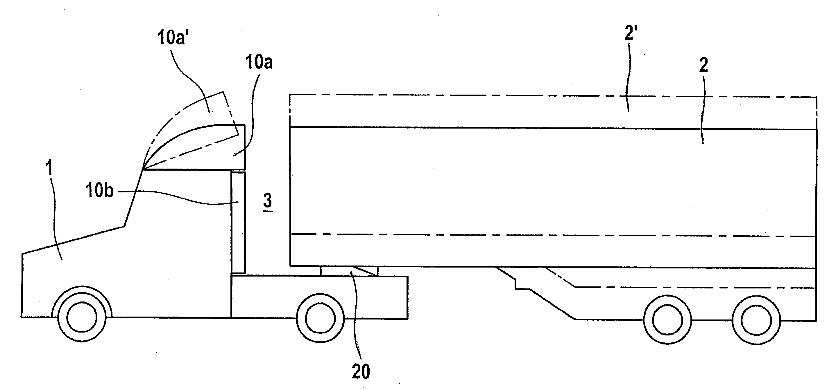
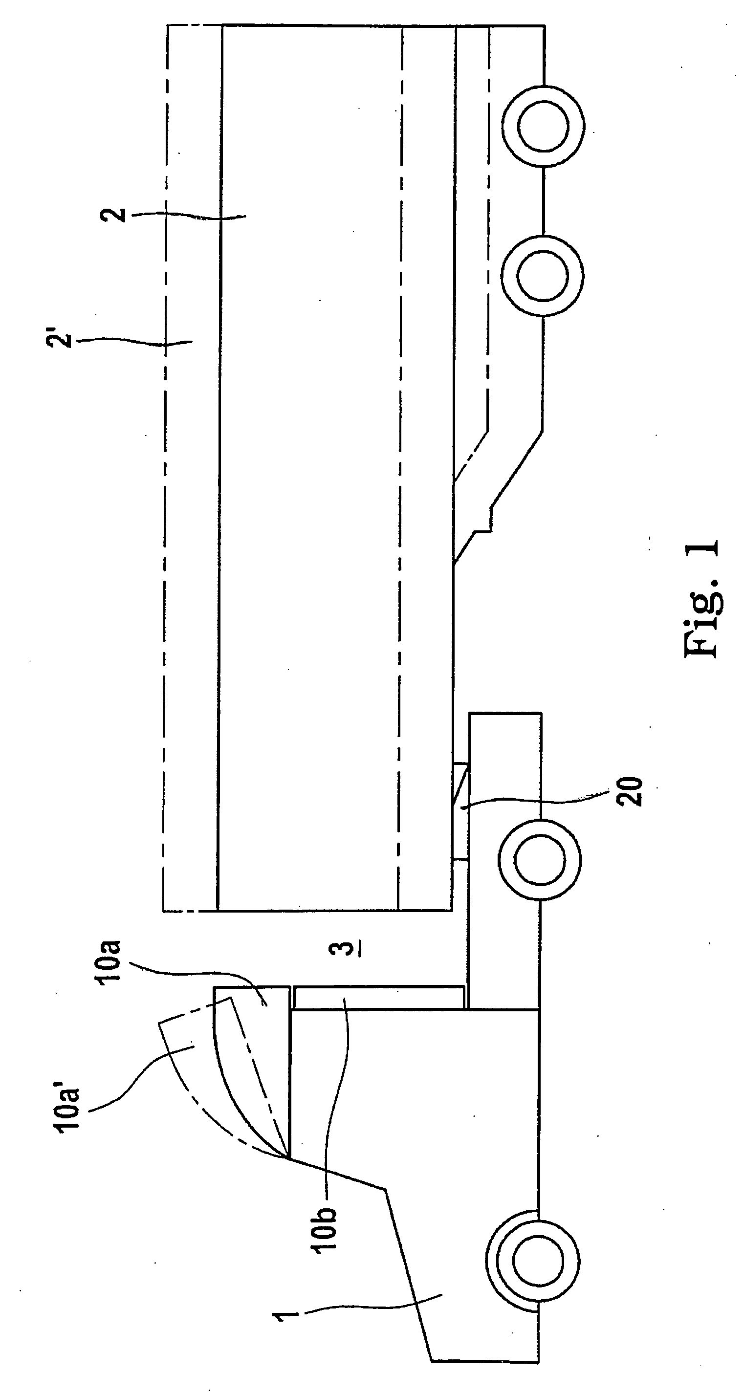
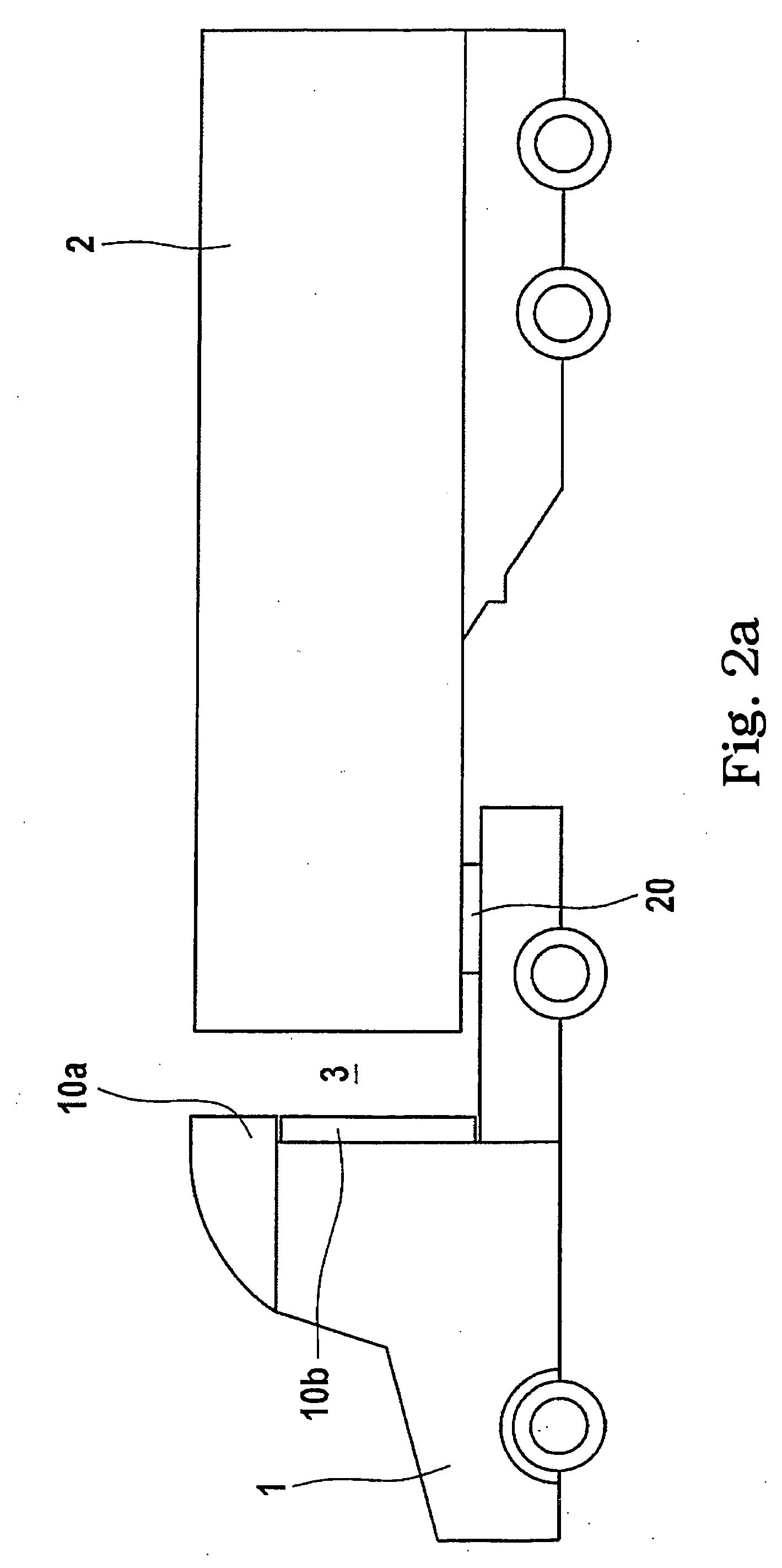
[0052]In FIGS. 1 to 3, a tractor and semi-trailer combination is illustrated which is comprised of a tractor vehicle 1 and a semi-trailer 2, in different positions. The Tractor 1 has an adjusting device 20 with a “fifth wheel” coupling disposed on it, which fifth wheel coupling engages the semi-trailer 2 via the main pivot of said semi-trailer. The adjusting device is shown only schematically in FIGS. 1 to 3. The tractor 1 bears a swingably adjustable wind deflector 10a on its roof 4, and lateral wind deflectors (10b) mounted on the cab of the tractor.

[0053]The semi-trailer 2 is shown in a raised position 2′ in dashed lines in FIG. 1, in connection with which situation the wind deflector 10a′ is in its upwardly swung position. To reduce wind resistance, the semi-trailer may be lowered to the position 2, in connection with which situation the adjusting device 20 and the frame of the semi-trailer are lowered. The said frame is lowered in particular via spring-loaded adjusting means, n...


PUM


Abstract

A device for adjusting a fifth wheel, comprising a displacement device provided with two guide rails placed on the vehicle, in particular on a tractor semi-trailer combination in the longitudinal direction thereof, said guide rails whereon a slide may be installed capable of being moved by means of an actuating device, said actuating device being designed such that, upon a displacement, the positive connection between the guide rails and the slide is maintained. The actuating device, which is designed to move the slide, comprises a first powered device. Additionally, at least one first position sensor is arranged to detect the position of the slide, at least said first position sensor being connected to a control device.

Description

CROSS REFERENCE[0001]This application is a division of U.S. application Ser. No. 11 / 662,008 filed Mar. 6, 2007, which is a 371 of PCT / EP05 / 09483 filed Sep. 3, 2005, which claims priority to German Patent Application No. DE 10 2004 045 862.3 filed Sep. 18, 2004, all herein fully incorporated by reference.FIELD OF THE INVENTION[0002]The invention relates to an adjusting device for a “fifth wheel” coupling for a semi-trailer. The invention further relates to a wind deflecting system disposed on the cab of the tractor of a tractor and semi-trailer combination, and to a control system for a tractor vehicle having a fifth wheel coupling. The invention further concerns a device for reducing the air resistance of a tractor and semi-trailer combination.BACKGROUND. OF THE INVENTION[0003]Displacement devices are known, e.g. from DE AS 1780488, EP 0503954 A1, and DE 19944684 C1.[0004]Further, WO 02 / 070328 A1 discloses a displacement device having two guide rails with toothed beams, wherewith a ...

Claims


Application Information

Patent Timeline
Patent Type & Authority Applications(United States)
IPC IPC(8): B62D35/00
CPCB62D35/001B62D53/0821B62D53/0814B62D53/068
Inventor ALGUERA, JOSE
Owner JOST WERKE GMBH
Learn More