Systems and Methods for Measuring the Shape and Location of an object

a technology of object shape and location, applied in the field of optical diagnostics, can solve the problems of data obtained, problem exacerbated, central region of corneal surface cannot be detected during the measurement,

Active Publication Date: 2009-06-25
AMO DEVMENT
View PDF99 Cites 148 Cited by
  • Summary
  • Abstract
  • Description
  • Claims
  • Application Information

AI Technical Summary

Problems solved by technology

In the field of ophthalmics, ocular aberrations of the eye typically produce unwanted results (bad eyesight) and therefore need to be characterized so as to be adequately treatable.
One problem in many Placido disk corneal topographers is that the central region of the corneal surface cannot be detected during the measurement because of the need to provide an opening or aperture in the Placido disk for passing the light reflected from the cornea to the detector array.
This is especially disadvantageous because the central optical zone of the cornea in particular determines the refractive power of the eye and typically forms the pass-through point of the visual axis.
As the opening or aperture is increased in size, this problem is exacerbated.
Another problem with Placido disk corneal topographers is that the data is obtained from analysis of a series of projected rings.
However, this only provides radial deviations.
While these are azimuthally resolved, they do not provide an adequate measure of the “skew” rays, i.e., those rays which would be deflected in an azimuthal direction.
This is an inherent limitation for a system using Placido rings.
This limitation is especially significant considering that astigmatism, one of the major classes of ocular aberrations, is known to generate significant skew rays.
Yet another problem in Placido-type systems in general, as well as types of optical measurement system (e.g, wavefront aberrometers) is alignment error (i.e., “vertex error”) between the corneal surface vertex and the design corneal vertex plane.
If an actual cornea being measured is “too close” or “too far” from the instrument, then there is a vertex error that will produce inaccurate corneal topography results, unless this vertex error can be determined and factored into the corneal topography calculations.

Method used


Image

  • Systems and Methods for Measuring the Shape and Location of an object
  • Systems and Methods for Measuring the Shape and Location of an object
  • Systems and Methods for Measuring the Shape and Location of an object

Examples


Embodiment Construction

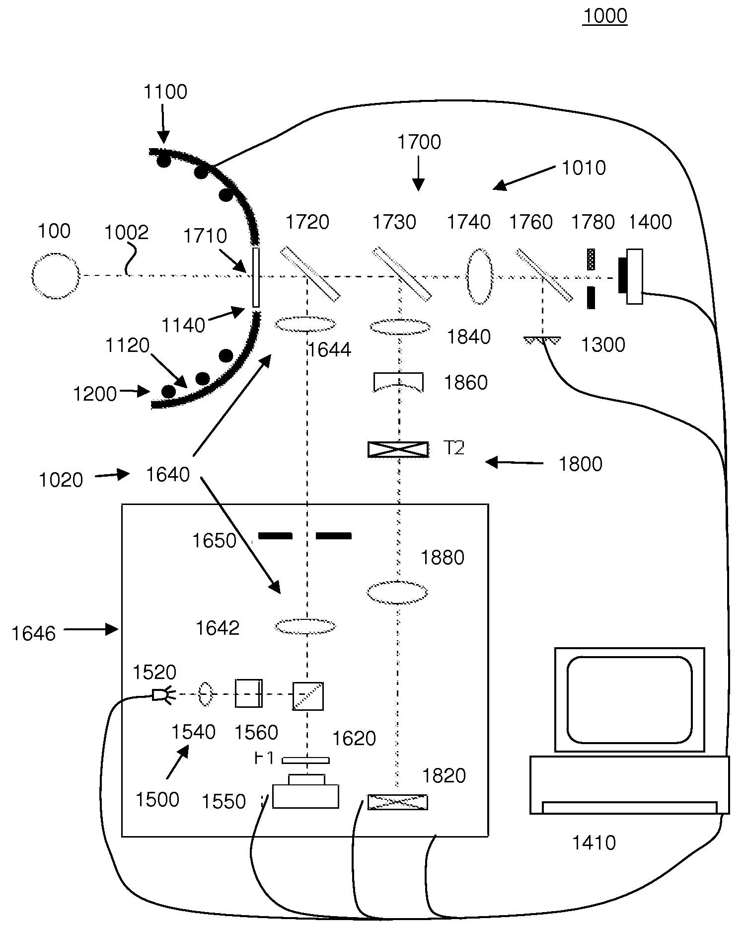
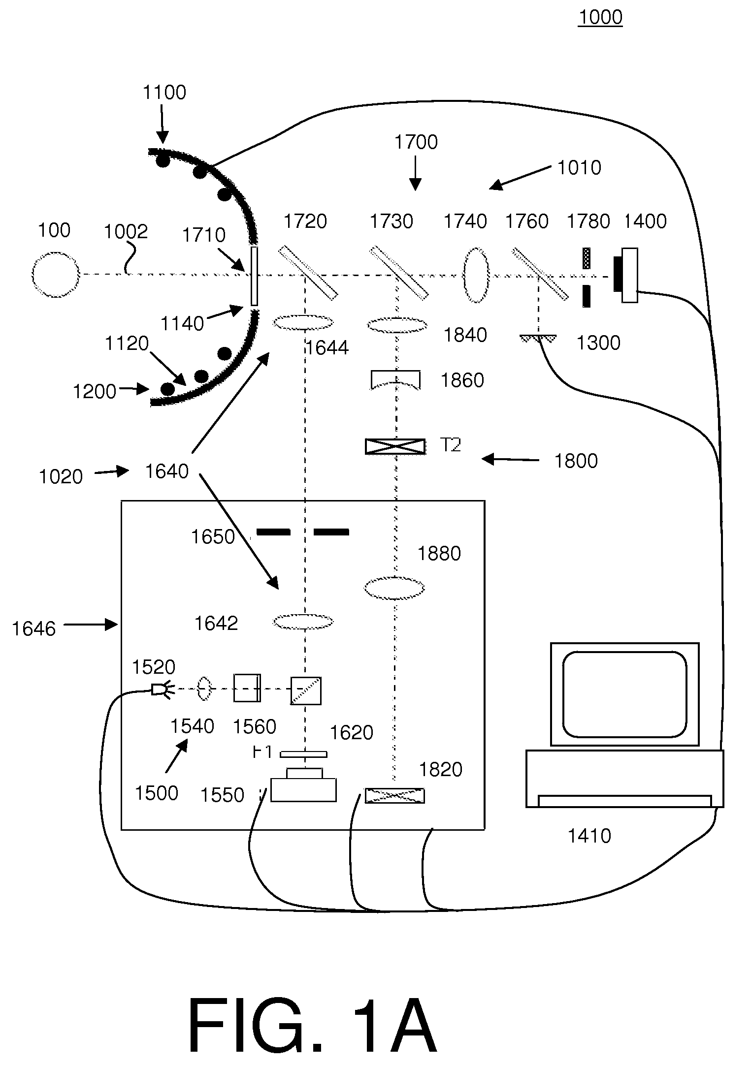
[0045]As discussed above, it would be desirable to provide systems overcome some of the problems associated with optical measurement systems such as vertex error. Such systems would be particularly beneficial in the areas of metrology and ophthalmic measurement. One example discussed in greater detail herein is a combined system for measuring aberrations and a corneal topography of an eye.

[0046]FIG. 1A shows one embodiment of a system 1000 for measuring aberrations and corneal topography of an eye 100. System 1000 comprises a topographer 1010, an aberrometer or wavefront analyzer 1020, and a processor 1410. The topographer 1010 comprises a structure 1100 having a principal surface 1120 with an opening or aperture 1140 therein; a plurality of first (or peripheral) light sources 1200 provided on the principal surface 1120 of the structure 1100; a plurality of second, or central, light sources 1300 (also sometimes referred to as “Helmholtz light sources”); and a detector, photodetector...


PUM


Abstract

A system for determining the shape of an object and / or a distance of the object from the system includes a first plurality of light source, a second plurality of light sources, and a detector or detector array. The first plurality of light sources are disposed about a central axis and are separated from the central axis by radial distances defining an aperture in the first plurality of light sources. The system also includes an optical system adapted to provide light from the second plurality of light sources through the aperture to the object. The system may further include a computer configured to determine the shape of the object and / or the distance of the object from the system using light from the first and second plurality of light sources that is reflected from the object and received by the detector.

Description

RELATED APPLICATION[0001]This application is a continuation-in-part of, and claims prior to, U.S. patent application Ser. No. 11 / 769,054, filed on Jun. 27, 2008, and further claims priority to U.S. provisional application No. 61 / 019,807, filed on Jan. 8, 2008, the entire contents of each of which applications are hereby incorporated by reference in their entirety for all purposes as if fully set forth herein.BACKGROUND AND SUMMARY[0002]1. Field[0003]This invention pertains to the field of optical diagnostics, and in particular to methods and systems for measuring the shape and location of an object such as a cornea of an eye.[0004]2. Description[0005]Optical diagnostic systems provide information of an object without the necessity of physical contact. For example, surface topography or optical characteristics of an eye or ophthalmic lens may be obtained using any of a variety of optical techniques, including optical topography, optical coherence tomography, interferometry, aberromet...

Claims


Application Information

Patent Timeline
Patent Type & Authority Applications(United States)
IPC IPC(8): G01B11/255G01B11/25G01M11/08A61B3/107G01C5/00
CPCA61B3/0091A61B3/107G01B11/255G01B11/25A61B3/145
Inventor CAMPBELL, CHARLES E.FARRER, STEPHEN W.NEAL, DANIEL R.POWERS, WILLIAM S.RAYMOND, THOMAS D.COPLAND, JAMES
Owner AMO DEVMENT
Why Eureka
Try Eureka