
Method of forming a phosphor or scintillator material and vapor deposition apparatus used therefor

Inactive Publication Date: 2009-06-25
T2PHARMA GMBH
View PDF18 Cites 7 Cited by
  • Summary
  • Abstract
  • Description
  • Claims
  • Application Information

AI Technical Summary

Benefits of technology

[0019]The above-mentioned advantageous effects have been realized by a method having the specific features as set out in claim 1.
[0020]Specific features for preferred embodiments of the invention are set out in the dependent claims.

Problems solved by technology

Such high amounts of raw material, deposited e.g. at the walls of the vapor deposition apparatus, moreover require recovering of expensive raw materials at a high cost.

Method used


Image

  • Method of forming a phosphor or scintillator material and vapor deposition apparatus used therefor
  • Method of forming a phosphor or scintillator material and vapor deposition apparatus used therefor

Examples


examples

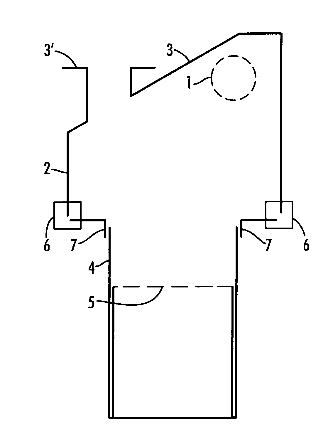
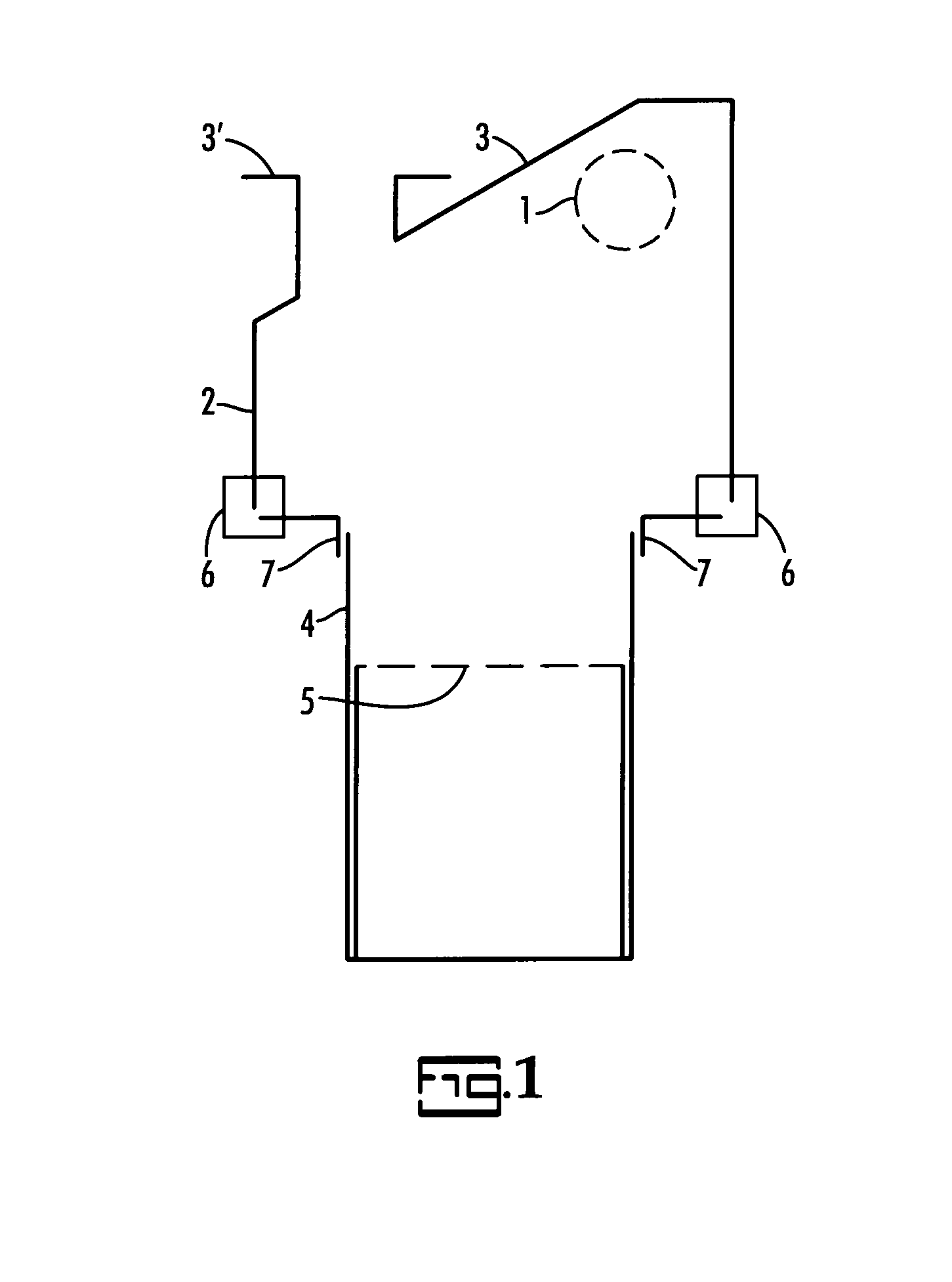
[0062]The crucible was in form of a boat having a length of 10 cm, a width of 35 mm and a height of 47.5 mm, composed of “tantalum” having a thickness of 0.25 mm, composed of 7 integrated parts, i.e. a crucible container (4), an internally heated chimney (2), a heat shield with slit (3) and a slot outlet (3′), an inner lid with small circular perforations (5) having a diameter of 2 mm, a ceramic ring as an isolator between crucible and chimney (6) and a “saving” or “reduction” part in order to fit crucible (4) to chimney (2).

[0063]The longitudinal parts were folded from one continuous tantalum base plate in order to overcome leakage and the head parts are welded. The chimney was provided with one linear infrared heater (quartz lamp) with a diameter of 10 mm (1) in order to heat the chimney in order to overcome condensation of vaporized materials. Moreover the chimney heater (1) was positioned in such a way that no direct heating of the substrate occurred, thanks to the position and ...


PUM

PropertyMeasurementUnit
Lengthaaaaaaaaaa
Lengthaaaaaaaaaa
Lengthaaaaaaaaaa

Abstract

In a method of preparing a storage phosphor or a scintillator layer on a support by vapor depositing from a crucible unit in a vapor deposition apparatus, while heating as phosphor or scintillator precursor raw materials a matrix component and an activator component or a precursor component thereof, said crucible unit comprises a bottom and surrounding side walls as a container for the said phosphor or scintillator precursor raw materials present in said crucible, said crucible is provided with an internal lid with perforations (5) and said crucible unit further comprises a chimney as part of the said crucible unit and a slit allowing molten, liquefied phosphor or scintillator precursor raw materials to escape in vaporized form under reduced pressure from said crucible unit in order to become deposited as a phosphor or scintillator layer onto said support; and at least one heating means (1) in the chimney (2) is positioned under a heat shield with a slit (3) and a slot outlet (3′), covering thereby said crucible unit and making part of said chimney (2), so that said heating means (1) cannot be observed when looking into the vaporization unit through said slot outlet (3′) from any point in the plane of the said support present as a vapor deposition target in the said vapor deposition apparatus and, while vaporizing said phosphor or scintillator precursor raw materials, a vapor cloud escapes from said slot outlet (3′) in the direction of the said support so that the ratio of the longest radius of the said vapor cloud versus the radius perpendicular thereto, when projected onto the phosphor or scintillator plate or panel from whatever an intersection through the said vapor cloud between slot outlet (3′) and support is at least 1.3, said intersection being taken parallel with the said support.

Description

FIELD OF THE INVENTION[0001]The present invention relates to a method of preparing a storage phosphor or scintillator plate by a vapor deposition process. More particularly the invention is related to vapor deposition from a dedicated crucible unit in a vapor deposition apparatus in order to optimize the steering of the vapor cloud while performing vapor deposition onto a support, mounted in the said apparatus.BACKGROUND OF THE INVENTION[0002]In a vapor deposition process, performed in a vapor deposition apparatus, following configurations in said apparatus are known from the prior art. The contents of all of the references cited is incorporated herein by reference.[0003]As described in WO 90 / 12485 an apparatus for use in a physical vapor deposition process comprises at least two evaporators with means in order to maintain each evaporator at an independent temperature, a temperature controlled collector, a vessel which embraces or communicates with the evaporators said vessel defini...

Claims


Application Information

Patent Timeline
IPC IPC(8): B05D5/06C23C16/00
CPCC09K11/7733C23C16/30C23C14/243
Inventor TAHON, JEAN-PIERRELEBLANS, PAUL
Owner T2PHARMA GMBH
Learn More