Biological substance detection cartridge,biological substance detection apparatus, and biological substance detection method

a technology of biological substance and detection cartridge, which is applied in the direction of specific use bioreactor/fermenter, biomass after-treatment, laboratory glassware, etc., can solve the problems of uneven reaction and inefficiency, and achieve the effect of increasing the amount of luminescent substance produced and easy to raise the detection sensitivity

Inactive Publication Date: 2009-06-25
SEIKO EPSON CORP
View PDF5 Cites 29 Cited by
  • Summary
  • Abstract
  • Description
  • Claims
  • Application Information

AI Technical Summary

Benefits of technology

[0010]In view of this, it is an object of the present invention to obtain a biological substance detection cartridge, biological substance detection apparatus, and biological substance detection method with which the reaction in the reaction vessel is prevented from becoming uneven, and reaction efficiency and detection sensitivity are higher.

Problems solved by technology

If bubbles are generated, they can impede contact between the probe gene and the gene in the specimen, which is a problem in that the reaction is uneven and inefficient.

Method used


Image

  • Biological substance detection cartridge,biological substance detection apparatus, and biological substance detection method
  • Biological substance detection cartridge,biological substance detection apparatus, and biological substance detection method
  • Biological substance detection cartridge,biological substance detection apparatus, and biological substance detection method

Examples


embodiment 1

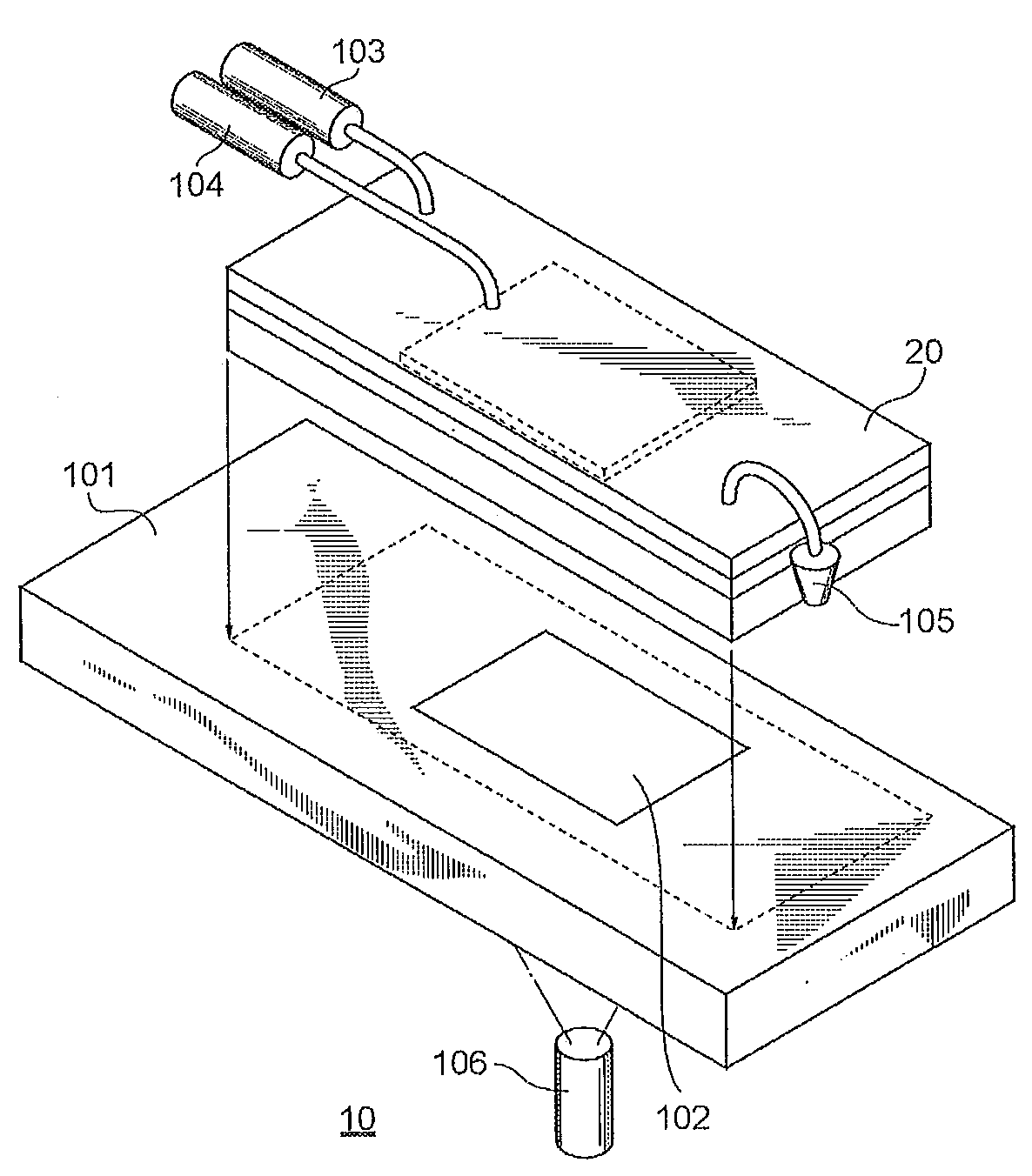
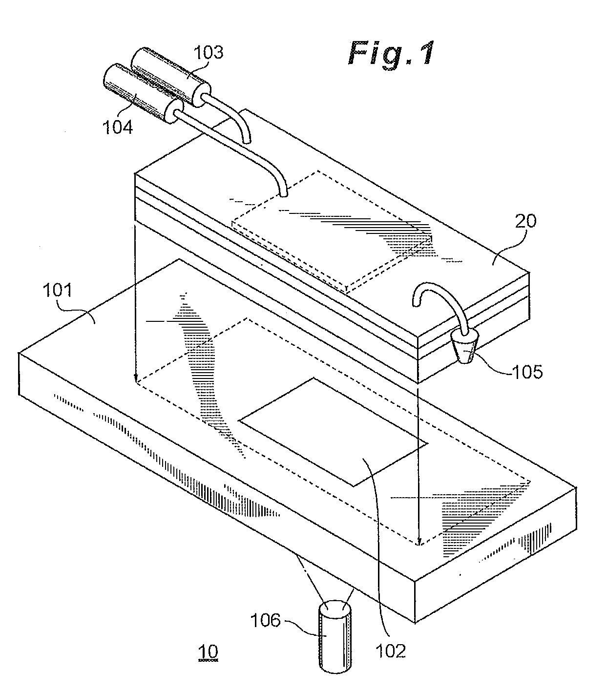
[0039]FIG. 1 is an oblique view of the simplified configuration of a nucleic acid detection apparatus (biological substance detection cartridge) 10 pertaining to Embodiment 1 of the present invention. As shown in the drawing, the nucleic acid detection apparatus 10 comprises a stage 101 on which is placed a detection cartridge (biological substance detection cartridge) 20, a detection window 102, a pump 103, a pump 104, a sample vessel 105, and a CCD camera 106.

[0040]The stage 101 is used to fix the detection cartridge 20. The detection window 102 is provided to the stage 101, and in detection in a hybridization reaction, the CCD camera 106 is used to measure the luminance intensity of the chemiluminescent substance produced in the detection cartridge 20.

[0041]The pumps 103 and 104 can be syringe pumps or micro-pumps, for example. The pump 103 is used to send the sample solution back and forth within the detection cartridge 20, while the pump 104 is used to discharge bubbles in the ...

embodiment 2

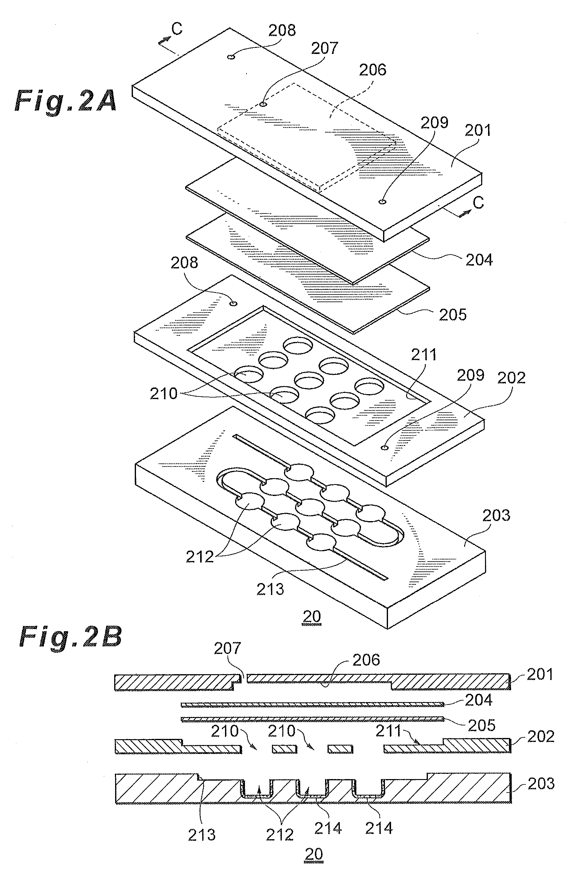
[0078]FIG. 5A is an exploded oblique view of a detection cartridge (biological substance detection cartridge) 30 pertaining to Embodiment 2 of the present invention, and FIG. 5B is a cross section along the C-C line in FIG. 5A.

[0079]As shown in the drawings, in Embodiment 2, a single reaction vessel 312 is formed instead of the plurality of chambers 212. Also, there is no plate 202, and the gas-liquid separation membrane 204 and the porous membrane 205 are flanked by the plate 201 and the plate 203.

[0080]As shown in FIG. 5B, the reaction vessel 312 is formed such that the plate 203 and the porous membrane 205 are superposed over one another, which results in the upper face being covered by the porous membrane 205. Further, by superposing the gas-liquid separation membrane 204 and the plate 201 over this, a configuration is achieved with which any air in the reaction vessel 312 is discharged by the air discharge component 206 through the gas-liquid separation membrane 204. Bubbles ge...


PUM

PropertyMeasurementUnit
depthaaaaaaaaaa
widthaaaaaaaaaa
lengthaaaaaaaaaa

Abstract

A biological substance detection cartridge, including: a reaction vessel for reacting a probe with a specific biological substance included in a sample solution, the reaction vessel having a region for fixing the probe for detecting the biological substance; a porous membrane facing the inside of the reaction vessel; a gas-liquid separation membrane superposed with the porous membrane; and a air discharge component which is provided on the opposite side of the gas-liquid separation membrane from the side contacting the porous membrane, and with which the interior can be kept at negative pressure during the reaction between the biological substance and the probe.

Description

CROSS-REFERENCES TO RELATED APPLICATIONS[0001]This application relates to and claims priority from Japanese Patent Application No. 2007-328434, filed on Dec. 20, 2007, the entire disclosure of which is incorporated herein by reference.BACKGROUND[0002]1. Technical Field[0003]The present invention relates to a biological substance detection cartridge, biological substance detection apparatus, and biological substance detection method for detecting a biological substance, such as a nucleic acid molecule having a specific base sequence.[0004]2. Related Art[0005]A DNA microarray is one method for assaying whether or not a specific gene originating in a disease is present in a specimen such as blood or tissue cells. With a DNA microarray, the presence of a target gene is detected by reacting (hybridizing) a probe gene affixed to a plate with a gene in a specimen. In the past, attempts have been made at raising reaction efficiency between the probe gene and the specific gene in the specime...

Claims


Application Information

Patent Timeline
Patent Type & Authority Applications(United States)
IPC IPC(8): C12Q1/68C12M1/00
CPCB01L3/502723B01L2200/0684B01L2300/02B01L2300/048B01L2400/0487B01L2300/0816B01L2300/087B01L2300/0887B01L2300/0636
Inventor KITAZAWA, RIETAKAGI, FUMIO
Owner SEIKO EPSON CORP
Why Eureka
Try Eureka