

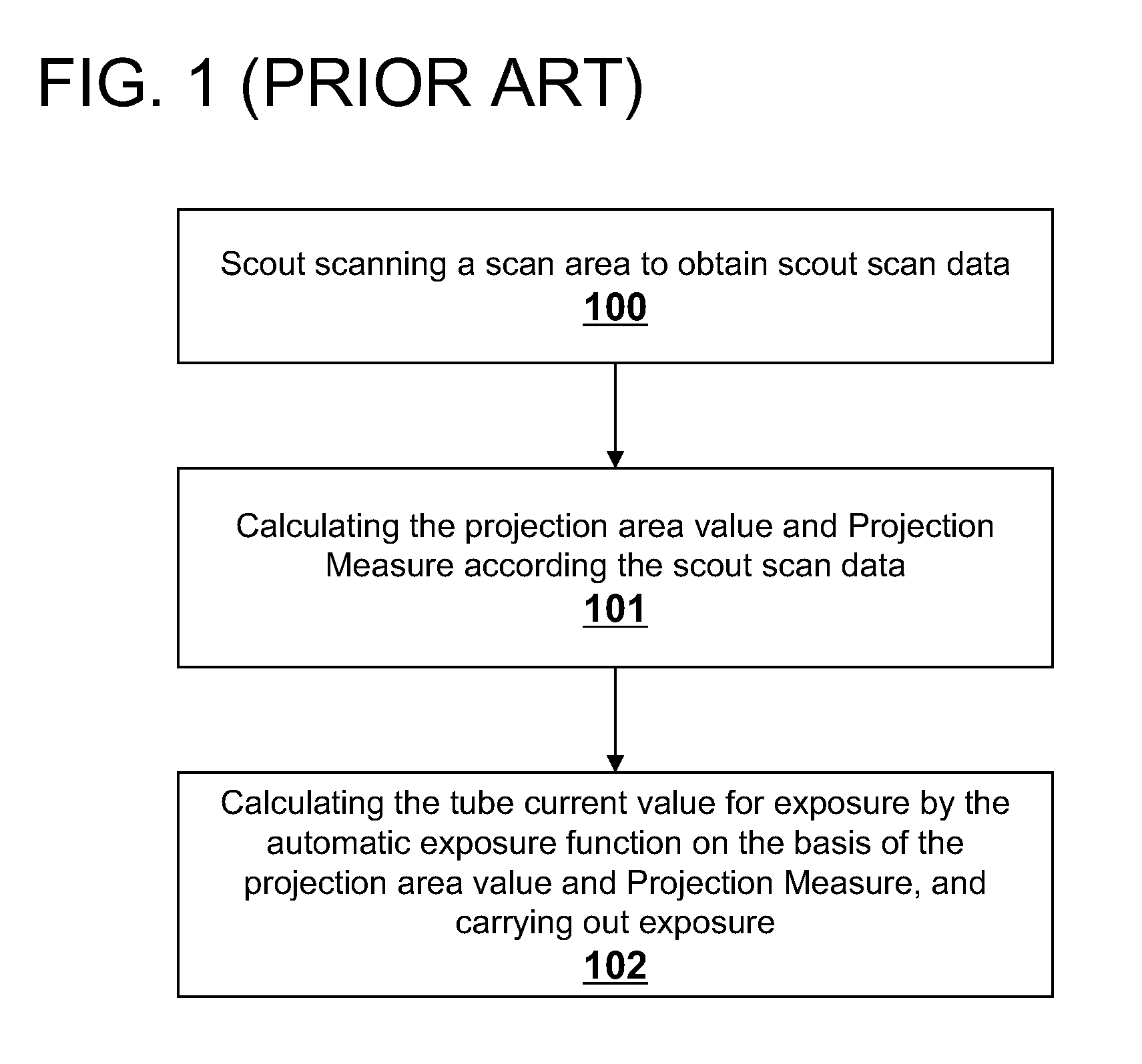
Method for controlling x-ray exposure in x-ray ct system
a ct system and x-ray technology, applied in the field of x-ray exposure control, can solve the problems of inability to accurately determine the state of an illness, discrepancy between the calculated the real projection area value of the slice, and the patient's unsatisfactory increase in the exposure of the patient to x-ray, so as to improve the stability and robustness of the exposure system
- Summary
- Abstract
- Description
- Claims
- Application Information
AI Technical Summary
Benefits of technology
Problems solved by technology
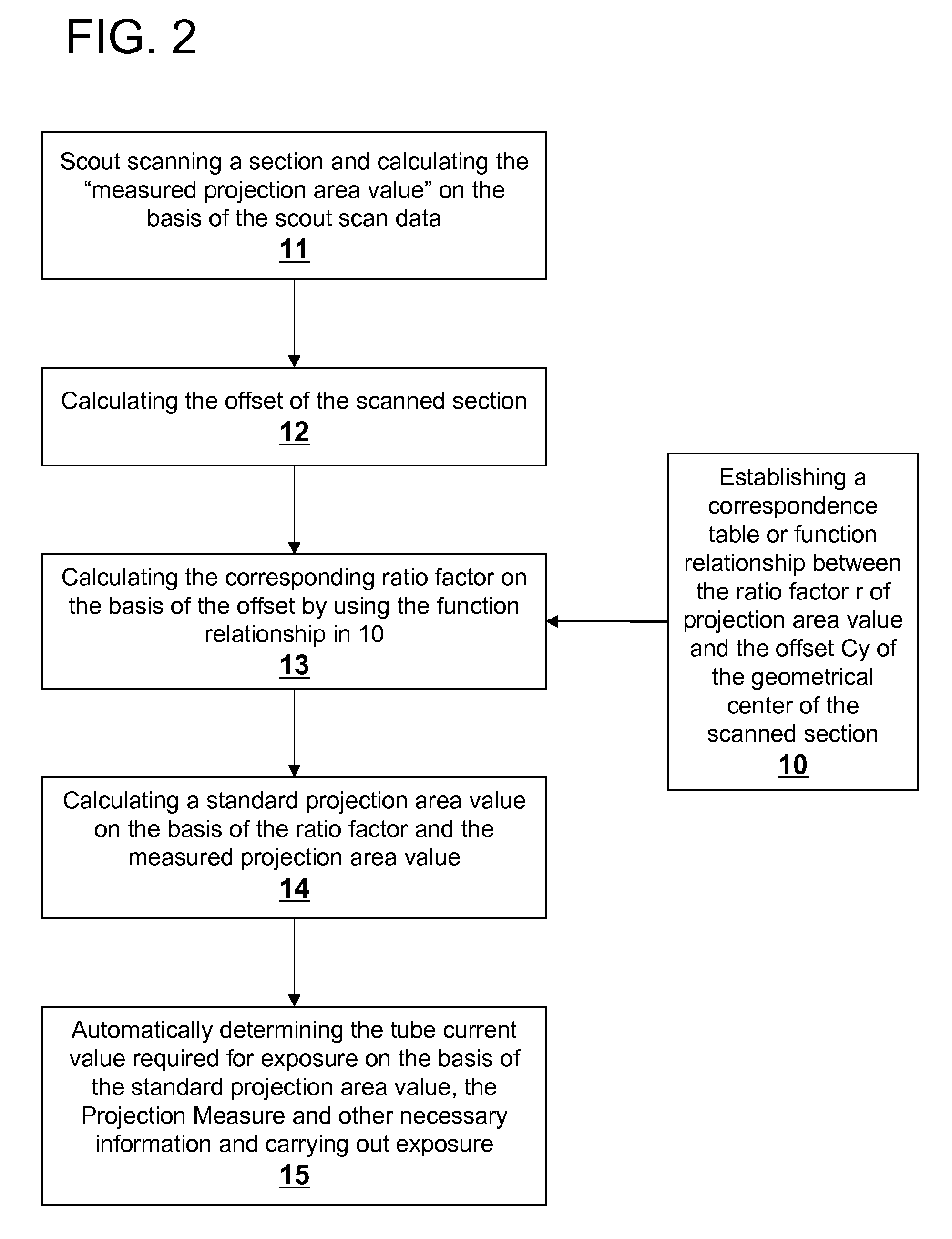
Method used
Image

Examples
first embodiment
[0051]Table 1 shows the application of the present invention wherein a polyethylene phantom B3 is scanned four times. First, the phantom B3 is placed at the rotation center ISO and is scout scanned at 0 degree and 180 degree, and corresponding projection area values are recorded. Then the phantom B3 is placed 60 mm below the rotation center ISO and scout scanned at 0 degree and 180 degree, and corresponding projection area values are recorded. Ratio factors to which offsets of +60 mm and −60 mm correspond can be looked up from Table 1, and the standard projection area values in the respective positions can be calculated. It can be seen from Table 1 that the standard projection area value thus calculated has an error less than 1.5% as compared to the actual projection area value obtained when the phantom is at the rotation center, and the errors in the range between ±2% are acceptable for all scanned phantoms.
TABLE 1Cypa(Cy)ra(Cy)pa(Cy = 0)error (%)02278.32160mm2527.41.12282250.97969...
second embodiment
[0052]FIG. 6 is a flow chart of the present invention for performing the automatic exposure control function. This embodiment calibrates in real-time the tube current required for the exposure of the current scanned section in an on-line manner. First, a scout scan is performed on the area to be scanned to obtain the scout scan data of the scanned section.
[0053]In step 20 the axial scan of the previous scan has finished but the axial scan exposure of the current slice has not started yet. In step 21 the standard projection area value of said previous slice is calculated on the basis of the projection data of the axial scan of the previous slice. In step 22 the “measured projection area value” of the previous slice and the “measured projection area value” and Projection Measure of the current slice are calculated on the basis of the projection data of the scout scan. In step 23 the ratio factor ra(Cy) of the previous slice is calculated on the basis of the standard projection area va...
embodiment 1
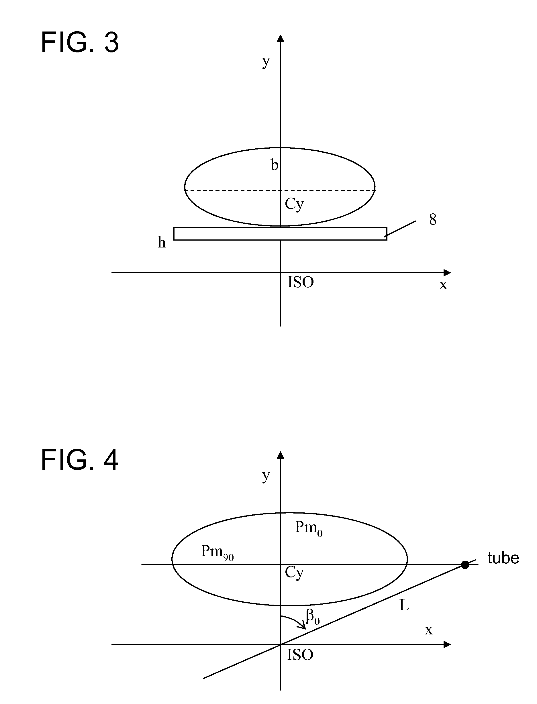
[0054]The standard projection area value of the previous slice (hereinafter represented by #(i−1)) can be obtained in step 21 by calculating the projection area value (pa(i−1,Cy)) of the previous slice #(i−1) at the offset (Cy) and the Projection Measure pm0 (related to the length of the short axis) when the tube is at 0 degree on the basis of the scout scan data during the scanning process of the previous slice #(i−1) in which the patient is placed at Cy. Returning to FIG. 4, the third method for calculating the offset in the embodiment 1 is used for finding the tube rotation angle β0 to which the maximum projection data value P(β0) corresponds. At the rotation angle β0, the X-ray at the channel having a fan-beam flare angle of ((π / 2−β0)) with respect to the central channel passes through the long axis of the elliptical slice being scanned, so information relating to the long axis of said ellipse can be obtained on the basis of the Projection Measure pm90 at said rotation angle β0....
PUM
 Abstract
Description
Claims
Application Information