Wound electrochemical device and method of manufacturing same

Active Publication Date: 2009-07-02
TDK CORPARATION
View PDF4 Cites 15 Cited by
  • Summary
  • Abstract
  • Description
  • Claims
  • Application Information

AI Technical Summary

Benefits of technology

[0015]By using a core material in which the smallest radius of curvature R0 in the curved part satisfies the relational expression mentioned above, the method of manufacturing an electrochemical device can manufacture the above-mentioned wound electrochemical device efficiently and reliably. Winding the electrode about the above-mentioned core material allows the smallest radius of curvature R in the curved part in the innermost circumferential portion to satisfy the condition of the above-mentioned expression (1) after the core material

Problems solved by technology

However, the inventors have found that, when a space is provided at the center portion of the wound body as described in the above-mentioned Japanese Patent Application Laid-Open No. 2003-109869, mechanical stresses caused by deformations in the space may be applied to parts (i.e., curved parts of the electrodes) securing the space, thereby adversely affecting characteristics of the electroc

Method used


Image

  • Wound electrochemical device and method of manufacturing same
  • Wound electrochemical device and method of manufacturing same
  • Wound electrochemical device and method of manufacturing same

Examples


Example

Example 1

Making of Electrodes

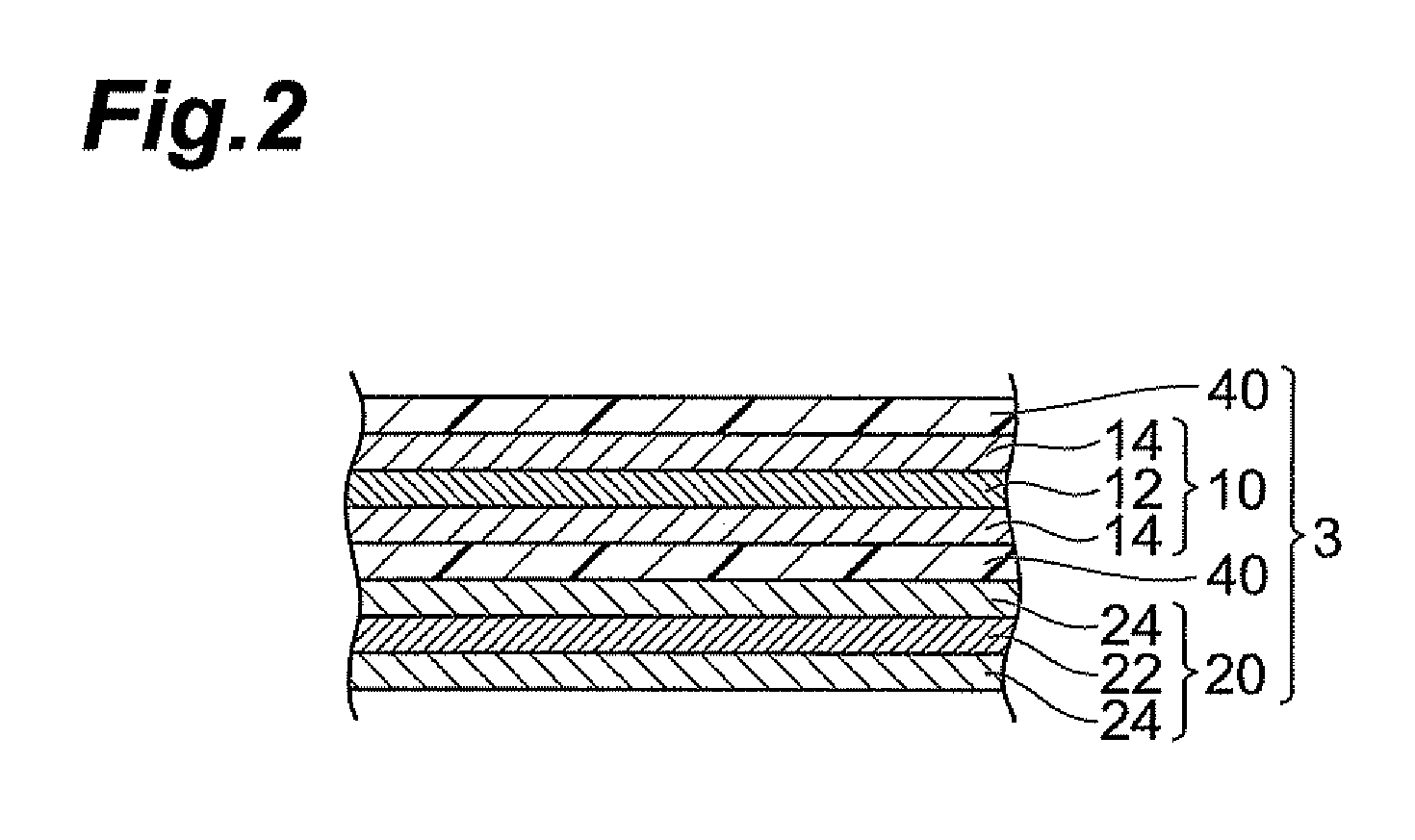
[0069]An active material layer coating liquid was prepared by mixing 87% by mass of granular activated carbon (product name: RP-20 manufactured by Kuraray Chemical Co., Ltd.), 3% by mass of acetylene black, and 10% by mass of polyvinylidene fluoride as a binder, and kneading the resulting mixture with N-methylpyrrolidone as a solvent. On the other hand, a lead made of an aluminum foil (having a thickness of 100 μm) was electrically connected to a band-like aluminum foil (having a thickness of 20 μm) by ultrasonic welding. Subsequently, the active material layer coating liquid was applied to both sides of the aluminum foil (having a thickness of 20 μm) by doctor blading and then dried, so as to form active material layers (each having a thickness of 8 μm). Thus, band-like electrodes (positive and negative electrodes) in which the active material layers each having a thickness of 8 μm were laminated on both sides of the current collector having a thickness...

Example

Examples 2 to 84 and Comparative Examples 1 to 42

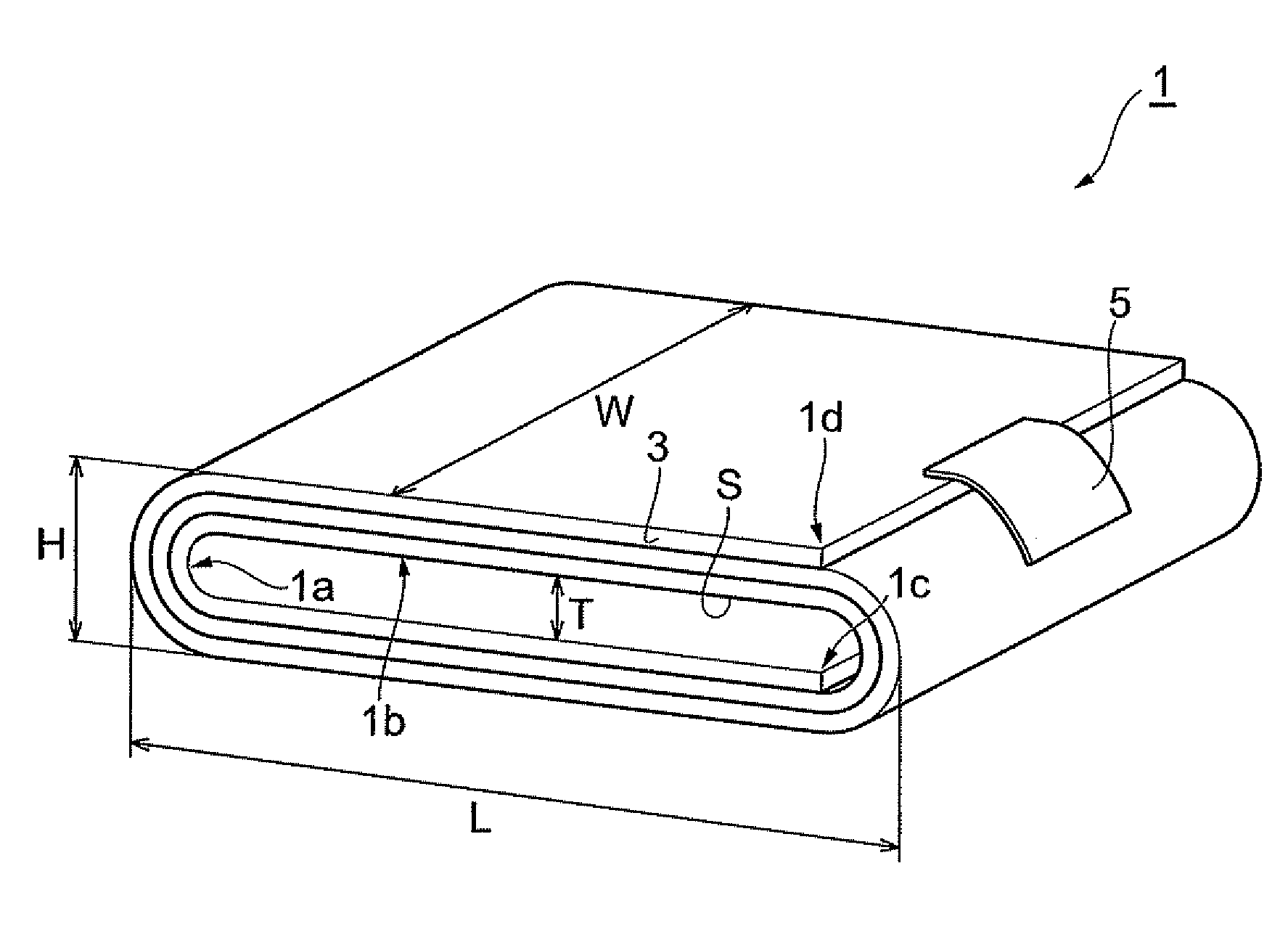
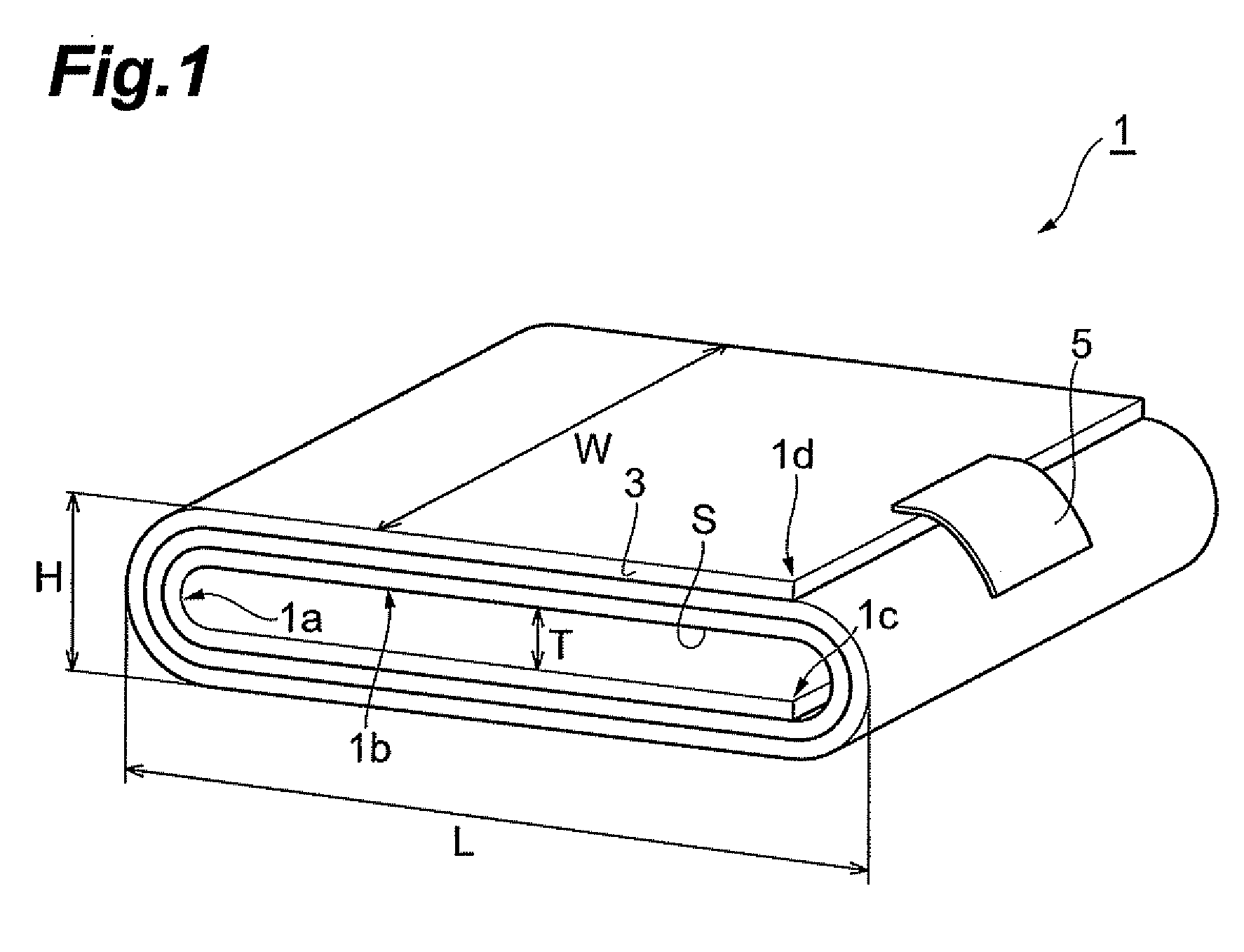
[0077]Wound electric double-layer capacitors of Examples 2 to 84 and Comparative Examples 1 to 42 were made as with Example 1 except that at least one of the thickness of the current collector, the thickness of the active material layer, and the form of the core material at the time of making the wound body was changed. Tables 1 to 4 show the values of the smallest radius of curvature R0 in the core materials and D0, D1, D2, (D0-D1), and (D0-D2) in the wound bodies of thus obtained wound electric double-layer capacitors. The smallest radius of curvature R of the curved part in the innermost circumferential portion of the wound body in each of the wound electric double-layer capacitors was the same as the smallest radius of curvature R0 in its corresponding core material.

[0078]Measurement of Capacity

[0079]Thus obtained electric double-layer capacitors were CV-charged at 3.3 V for 5 min and then CC-discharged at 5 mA from 3 to 2 V, and ...


PUM


Abstract

A wound electrochemical device has a wound body formed by winding a multilayer member including a multilayer structure composed of a positive electrode, a separator, and a negative electrode; wherein each of the positive and negative electrodes, includes a structure having an active material layer formed on both sides of a current collector; wherein the wound body has a space at a center portion thereof; and wherein the smallest radius of curvature R of a curved part in an innermost circumferential portion of the wound body satisfies the following expression (1):
R=α×(T1+2T2)  (1)
where R is the smallest radius of curvature of the curved part in the innermost circumferential portion of the wound body (unit: μm), α is a value within the range of 3.33 to 7.12, T1 is a thickness of the current collector of the electrode positioned at the innermost circumference of the wound body (unit: μm), and T2 is a thickness of the active material layer of the electrode positioned at the innermost circumference of the wound body (unit: μm), T2 being a value within the range of 8 to 30 (unit: μm).

Description

BACKGROUND OF THE INVENTION[0001]1. Field of the Invention[0002]The present invention relates to a wound electrochemical device and a method of manufacturing the same.[0003]2. Related Background Art[0004]Conventionally known wound electrochemical devices include those of a type using an elliptical or flat “″planar wound body” formed by flatly winding a long electrode (see Japanese Patent Application Laid-Open Nos. 2007-194130, 2006-286431, 2000-67907, and 2001-345115). In this type, the flat portion realizes a multilayer structure of electrodes, while bent portions formed upon winding can keep a mechanical strength of the electrodes and suppress deformations thereof. They have a flat form after winding and thus are advantageous in terms of space for use. However, it is necessary for electrodes to connect with leads having a specific thickness, which makes them hard to attain a significantly flat form.[0005]For such a problem, in order to securely attain a flat form, it has been prop...

Claims


Application Information

Patent Timeline
IPC IPC(8): H01M6/00H01M4/02H01G11/00H01G11/84H01M10/04H01M10/0587
CPCH01G9/151H01M10/0587H01M10/0431Y02E60/10Y02P70/50
Inventor OHASHI, YOSHIHIKOKOUGO, MITSUOHINOKI, KIYONORIKATAI, KAZUO
Owner TDK CORPARATION
Why Eureka
Try Eureka